and start-up
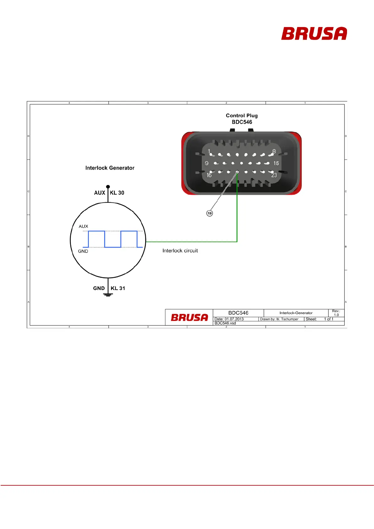
6.8 Interlock signal
The interlock signal is to be guided through all HV-carrying connectors in a HV system. The signal of the BDC546
can be evaluated via pin 19 of the control connector. A rectangular signal frequency of 86 Hz ≤ f ≤ 90 Hz is
regarded by the component as permissible. The range of a valid duty cycle lies between 48 % and 52 %. The
signal is to be generated from AUX/terminal30 (logic “HIGH”) and GND/terminal31 (logic “LOW”). An invalid signal
sequence is regarded as error state and potential operation of the component is prevented by deactivation of the
power stages. If it is required, this function can also be deactivated.
 Loading...