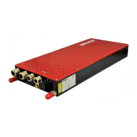
EasyManua.ls Logo

Brusa BDC546 - Control Connector Pin Assignment (Device Side)

Brusa BDC546
87 pages
Print Icon
To Next Page IconTo Next Page
To Previous Page IconTo Previous Page
Loading...
35
Technical data
and start-up
BDC546
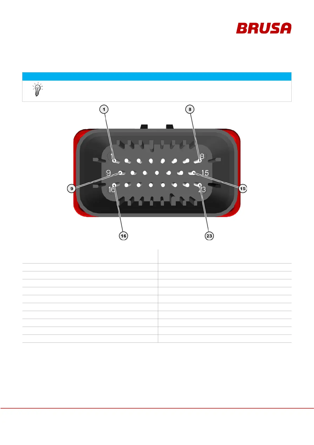
7.1 Control connector pin assignment (device side)
INFORMATION
Information on the pins required and/or recommended for operation or necessary for
programming
can be found in chapter 8.1 Control connector
1.
GND
Signal ground
(Minus wiring system, terminal 31)
2.
AUX
+12 V
(Plus wiring system, terminal 30)
3.
NC
Not connected
4.
NC
Not connected
5.
NC
Not connected
6.
TXD
RS232 Transmit (9 pole D-Sub: pin 2)
7.
RXD
RS232 Receive (9 pole D-Sub: pin 3)
8.
P_GND
RS232 ground (9 pole D-Sub: pin 5)
9.
CNL
CAN low
10.
CNH
CAN high
11.
PFO_VC+
Pyrofuse output VC+ (+12 V)
12.
PFI_VC+
Pyrofuse input VC+ (open drain)
13.
PRO
Enable firmware download
14.
PFO_VC-
Pyrofuse output VC- (+12 V)
15.
PFI_VC-
Pyrofuse input VC- (open drain)
16.
EN
Enable (power ON, terminal 15)
17.
DO_MC
Digital main contactor output
18.
NC
Not connected
19.
IL
HV interlock input
20.
NC
Not connected
21.
NC
Not connected
22.
NC
Not connected
23.
NC
Not connected

Table of Contents

Related product manuals