and start-up
8 Connections
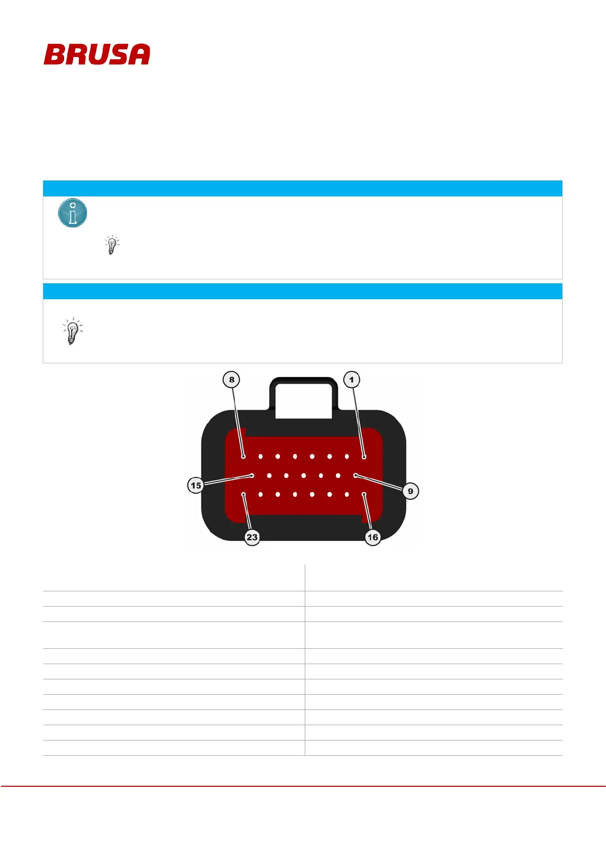
8.1 Control connector
The control connector has been designed for a maximum number of 10 cycles of connector
operation! The manufacturer guarantees the full functioning (conductance,
quantity.
For a professional mounting of the AMPSEAL contacts SN/LP, we recommend the usage of the
following crimping tool: Tyco 58440-1
Control connectors included in the scope of delivery are to be converted in accordance with the
respective requirements (EMC, environmental impacts etc.). Here, only the actually used pins are to
be wired (mandatory* or highly recommended**).
Pin 16 EN is to be connected to pin 2 AUX via a switch (e.g.: in the vehicle by means of
key with the Plus wiring system).
Signal ground
(Minus wiring system, terminal 31)
+12 V
(Plus wiring system, terminal 30)
RS232 Transmit (9 pole D-Sub: pin 2)
RS232 Receive (9 pole D-Sub: pin 3)
**
RS232 ground (9 pole D-Sub: pin 5)
Enable (power ON, terminal 15)