and start-up
8.2 Highside cable
Danger of death!
Before starting the manufacturing process, ensure that the power cables are de-energised.
To assemble the cable lugs, an appropriate crimping tool must be used! We recommend the
following crimping tool:
Klauke ultra EK 120 UNV-L
The cable lugs included in the scope of delivery are to be assembled with cables in accordance with
the following specifications. On request, this process may also be carried out by BRUSA.
For installation of a shielded cable with connection to the shielding braid, refer to chapter
9.2 Building the HV wiring
In case of longer cable lengths then 1.5
m consult the manufacturer BRUSA.
4.5 Manufacturer contact information.
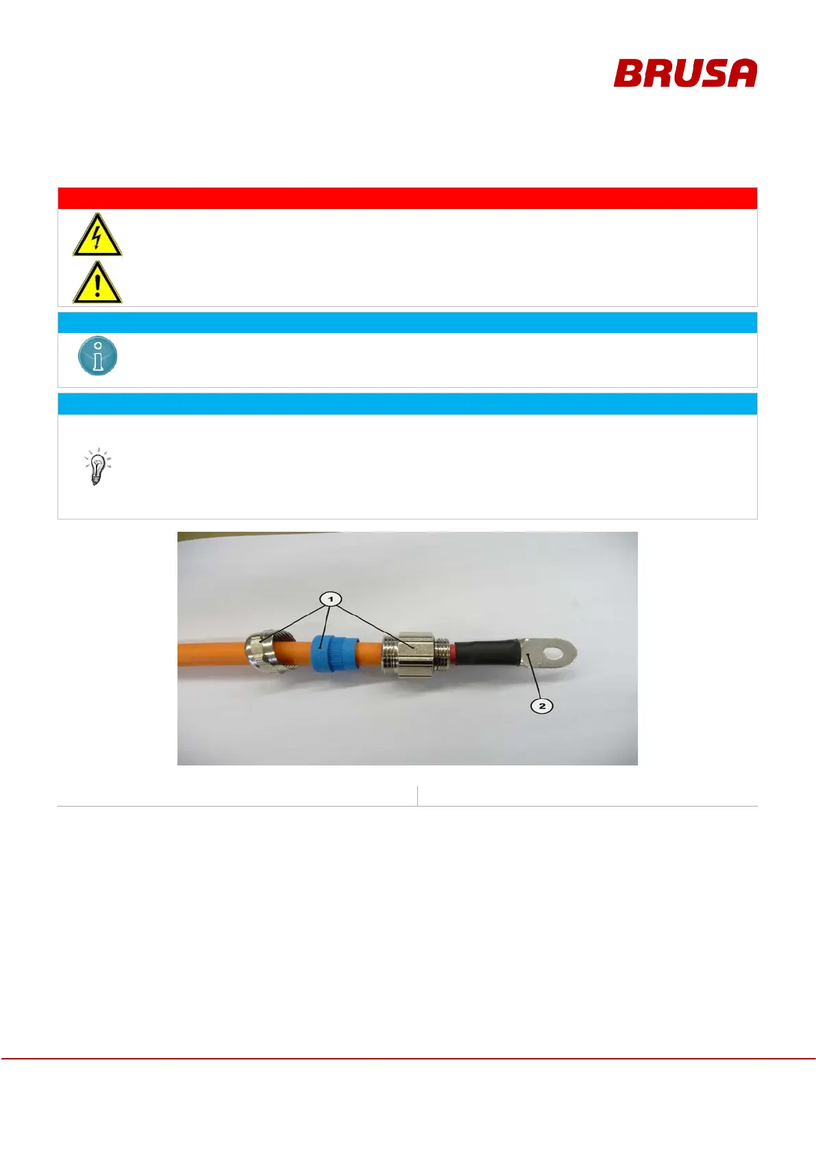
1. M25 cable fittings (HS)
2. Cable lug, flat (HS), 70 mm²
In order to guarantee reliable operation of all controllers - in particular of the HV voltage controller in boost mode -
the following instructions are to be strictly adhered to:
Required cable cross section: 70 mm²
Max. cable length between device and connected load/source = 1.5 m
Guide the cable fitting (1) over the power cable.
Square crimping of the cable lug (2).
Each prepared cable has to be checked for proper fitting of the cable lug and if for proper fastening of the
crimping (pull test).
When installing the cables (Highside plus and minus) in the vehicle, ensure that the spanned area remains as
small as possible and that no sensitive control signals are implemented in between.