Introduction
SMART MATRIX MTC - ii -
How to Use this Manual
The manual is subdivided into 3 sections:
Section 1 – includes the connection diagrams and the electrical interface of the various connectors.
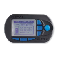
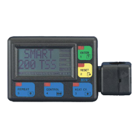
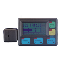
Section 2 – provides the operating instructions for a correct use of the SMART MATRIX MTC terminal as
well as the parameter configuration/programming instructions and data/errors display
facilities.
Section 3 – describes the main characteristics and performances of the various system components
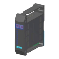
(IS3W/MTC sensors, SM-DIN MTC boards, DAC devices.). Furthermore, it provides some
details to better understand the operating principles upon which the SMART MATRIX MTC
system is based.
Symbols Used
This symbol is used to point-out notes, warnings and other important information.
MTC Within this manual, the IS3W/MTC sensors used for SMART MATRIX MTC application will be
indicated with the generic wording MTC
In the program function descriptions, this symbol indicates the function
(e.g. MTC IDENT.) within the menu item (e.g. SETUP).
SETUP
→
MTC IDENT.