42
EN
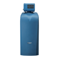
Firmlyinserttheushingwaterhoseintotheushing
water connection elbow (9).
Routetheushingwaterhoseataninclinetothe
sewagesystemconnection(drain)andsecurethe
endwiththexingmaterialsuppliedtopreventit
“appingabout”whenunderpressure.
Attachtheoverowhose(18x24)totheoverow
(10).Secureitwithcabletiesandrouteitwithan
incline of at least 10 cm to the sewage system
connection(drain).
A bypass is integrated into Multiblock X. The unit
canbeinstalledinhorizontalorverticalpipelines.
Follow the separate installation instructions for the
Multiblock; otherwise, warranty claims are void if
the unit becomes damaged.
Rinse out any dirt particles by opening the
handwheel on Multiblock X.
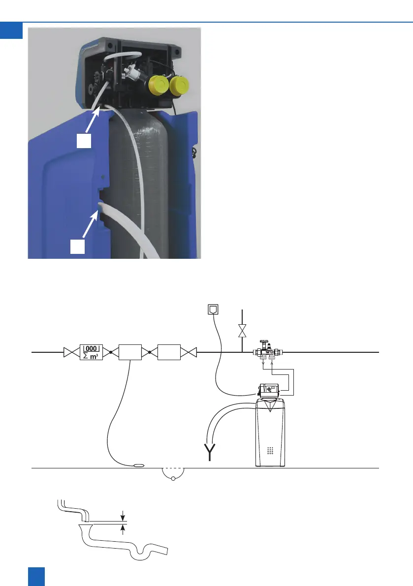
> 20 mm
6.1 Installation diagram
Strainer
Floor
sensor
Sewage
system
connec-
tion
Water
stop
9
10
Install the product as shown in the drawing. The
ushing water and overow hoses must not be
connected or constricted at any point.
Attachtheushingwaterandoverowhosestothe
sewage system connection at least 20 mm above
the highest possible waste water level.