56
NICE - MIRIAM - CRISTAL - LEONORA - PRETTY - DIANA - KRISS - MARY
EN
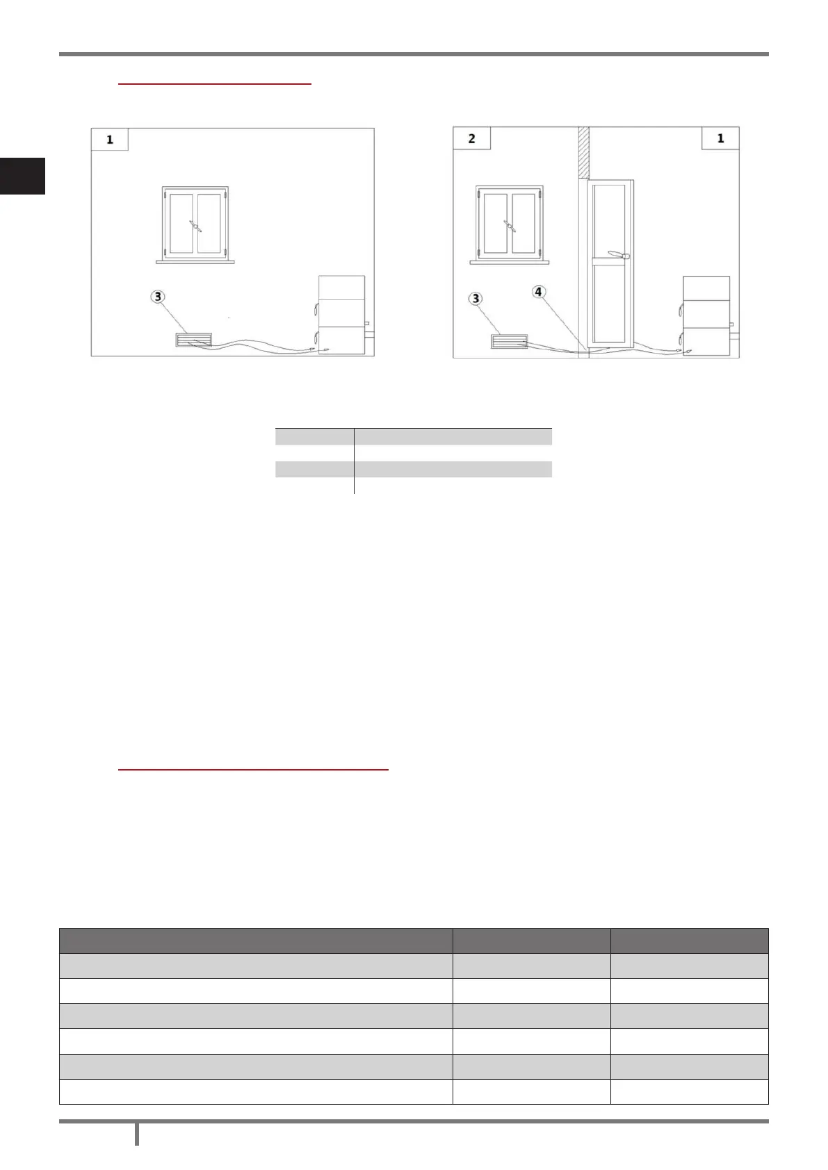
7.8 EXTERNAL AIR INLET
Fig. 7 - Direct air inow Fig. 8 - Indirect air inow
LEGEND Fig. 7 page 56|Fig. 8 page 56
1 Room to ventilate
2 Adjacent room
3 External air inlet
4 Cleft under the door
• The room must be endowed with an external air recycling for a good climate in your ambient.
• The air inow from outside to the inner occurs directly, through an opening on the external wall of the
room (see Fig. 7 page 56); otherwise it occurs indirectly by air suction from rooms adjacent to the one
to ventilate (see Fig. 8 page 56).
• Bedrooms, garages, and store of ammable materials are excluded.
• The air inlet should have a total net surface of 80 sqcm2: the aforesaid surface is to widen if inside the
room there are other activated appliances (for example: electric ventilators for foul air suction, cooker
hoods, other stoves, etc...) which depress the environment.
• At switched on appliance it is necessary to check that the pressure fall between the room and the
outside does not exceed 4,0 Pa value: if necessary widen the air inlet (EN 13384).
• The air inlet must be realized at a height close to the oor with an external grid against birds. In such a
way it cannot be obstructed by any object.
• In case of installation with sealed-chamber the air inlet is not necessary.
7.9 CHIMNEY FLUE CONNECTION
Your pellet stove works through a fume draught forced by a fan. It is obligatory to check that all pipes are
realized in compliance with the following regulation on material selection: EN 1856-1, EN 1856-2 e UNI/TS
11278. All must be effected by specialized personnel or companies as provided by UNI 10683:2012.
• The connection between the appliance and the chimney ue should be short in order to favor the
draught and to avoid condensation in the pipes.
• The fume conduit should be equivalent or longer than the outlet joint ones (Ø 80 mm).
• Some stove models are endowed with a lateral and/or back exhaust. Check that the unused exhaust is
sealed with the plug given with standard equipment.
SYSTEM TYPE Ø80 mm PIPE Ø100 mm PIPE
Minimum vertical length 1,5 mt 2 mt
Maximum length (with 1 union) 6,5 mt 10 mt
Maximum length (with 3 unions) 4,5 mt 8 mt
Maximum number of unions 3 3
Level section (minimum inclination 3%) 2 mt 2 mt
Installation at a height above 1200 m a.s.l. NO Obligatory
 Loading...