I)
Suspension Seat
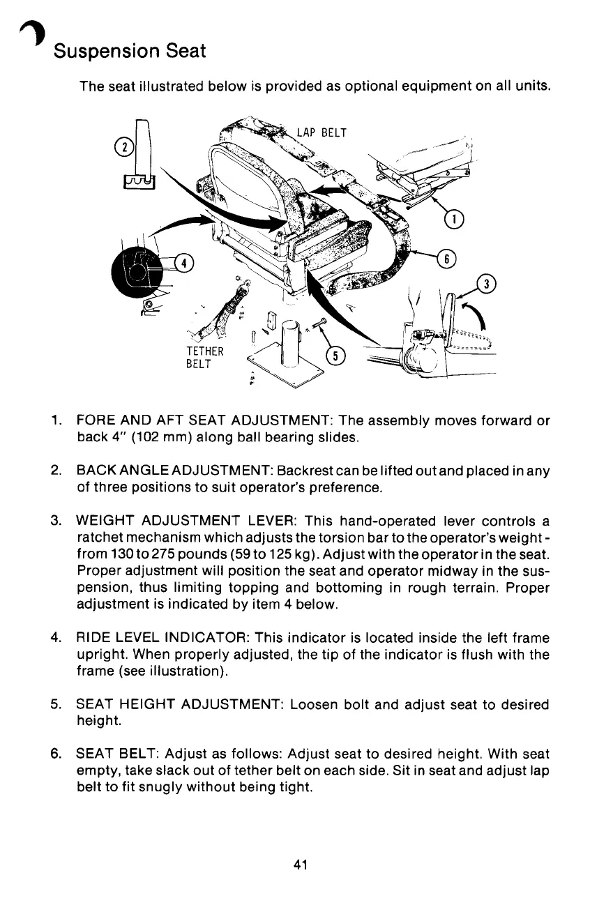
The seat illustrated below is provided as optional equipment on all units.
1. FORE AND AFT SEAT ADJUSTMENT: The assembly moves forward or
back 4" (102 mm) along ball bearing slides.
2. BACK ANGLE ADJUSTMENT: Backrest can be lifted out and placed in any
of three positions to suit operator's preference.
3. WEIGHT ADJUSTMENT LEVER: This hand-operated lever controls a
ratchet mechanism which adjusts the torsion bar to the operator's weight-
from 130to 275 pounds (59 to 125 kg). Adjust with the operator in the seat.
Proper adjustment will position the seat and operator midway in the sus-
pension, thus limiting topping and bottoming in rough terrain. Proper
adjustment is indicated by item 4 below.
4. RIDE LEVEL INDICATOR: This indicator is located inside the left frame
upright. When properly adjusted, the tip of the indicator is flush with the
frame (see illustration).
5. SEAT HEIGHT ADJUSTMENT: Loosen bolt and adjust seat to desired
height.
6. SEAT BELT: Adjust as follows: Adjust seat to desired height. With seat
empty, take slack out of tether belt on each side. Sit in seat and adjust lap
belt to fit snugly without being tight.
41