1-18
28. The engine is equipped with a fuel injection system consisting of an engine driven fuel
pump, a fuel/air control unit, a fuel manifold, a fuel flow indicator, and air bleed type injector
nozzles. Some key characteristics of the fuel injection system are:
a. fuel is delivered by the engine driven pump to the Fuel / Air Control Unit (FACU)
on the bottom of the engine. The FACU proportions the fuel flow to the induction
air flow, which is controlled by the throttle;
b. the FACU contains a mixture control valve which is directly connected to the
cockpit mixture control;
c. vapour and excess fuel from the engine driven pump and the FACU are returned
to the RH fuel tank by a vapour return line;
d. air is delivered to the cylinders through intake manifold tubes and metered fuel is
delivered by the FACU to the fuel manifold on the top of the engine;
e. the fuel manifold evenly distributes the fuel to an air bleed type injector nozzle in
the intake valve of each cylinder; and
f. a pressure line is connected to the fuel manifold and provides fuel pressure
indications to the EDM 930 display.
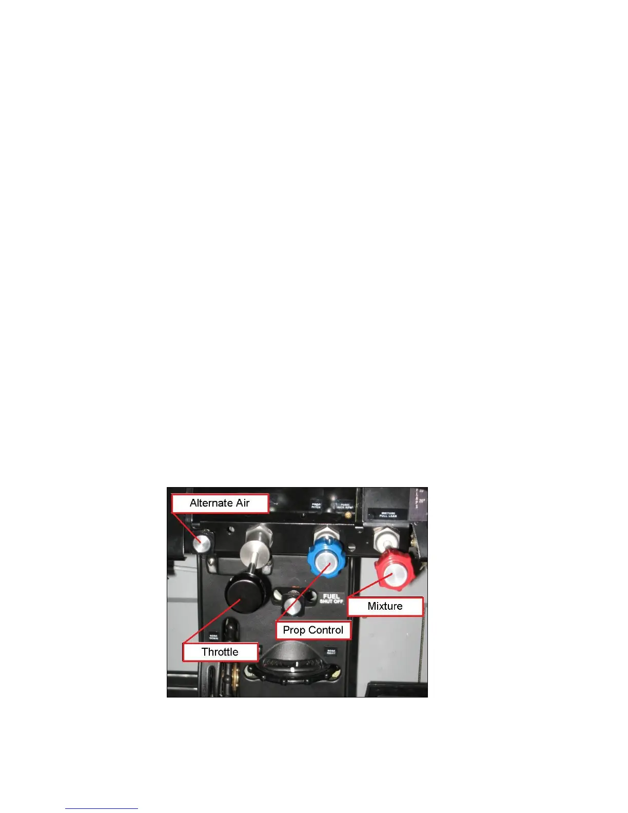
29. The three primary power-plant controls (throttle, propeller, mixture) are push/pull
actuators centrally located on the lower instrument panel. They are colour coded and each has
a distinctive shape for ease of visual and tactile recognition.
Figure 1-25 Power Unit Controls