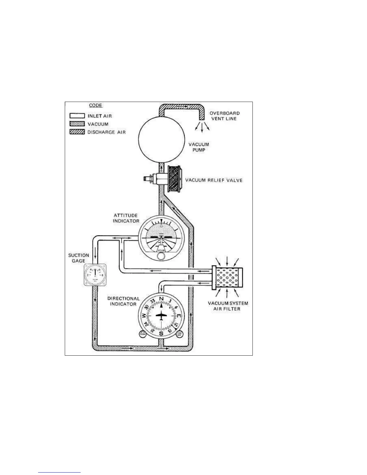
86. An engine driven vacuum pump provides the suction necessary to operate the attitude
indicator and directional indicator. The system incorporates a vacuum relief valve and air filter.
A suction gauge located to the left of the flight instruments is calibrated in inches of mercury
and indicates the suction currently available. A suction range of 4.5 to 5.5 in-Hg is desired for
reliable operation of the attitude indicator and directional indicator.
87. A vane type stall warning unit is located in the left wing leading edge which electrically
activates an audible stall warning horn located under the instrument panel. The horn is not
connected to the intercom system. The horn is activated at speeds approximately 5-10 mph
above the stall in all configurations.