Emotron VS Series Quick Start Guide
- 108 -
Set value corresponding
to input of inflection
point 2 of curve AI1
Maximum input of curve
AI1
Range: Input of inflection point
2 of curve AI1~100.0%
Set value corresponding to
maximum input of curve AI1
Curve AI1 is defined by above-noted 8 parameters.
Input values C2.00, C2.02, C2.04, C2.06:
AI1~AI2 are 0~10V or 0~20mA programmable by jumper on control board.
If 0~10V is selected: 0V corresponds to 0%, while 10V corresponds to 100%.
If 0~20mA is selected: 0mA corresponds to 0%, while 20mA corresponds to 100%.
AI3 only supports -10V~10V input; For AI3, -10V corresponds to -100%, while 10V corresponds
to 100%.
Corresponding set values C2.01, C2.03, C2.05, C2.07:
When the corresponding set value is frequency: 100% is the maximum frequency, while
-100% is the maximum negative frequency.
When corresponding set value is torque: 100% means 2 times the rated torque, while -100%
Means negative "2 times the rated torque".
When the corresponding set value is output voltage (e.g. the voltage setting in case of V/f
separated pattern): 100% corresponds to rated voltage of motor. "Less than or equal to 0%"
corresponds to 0V voltage.
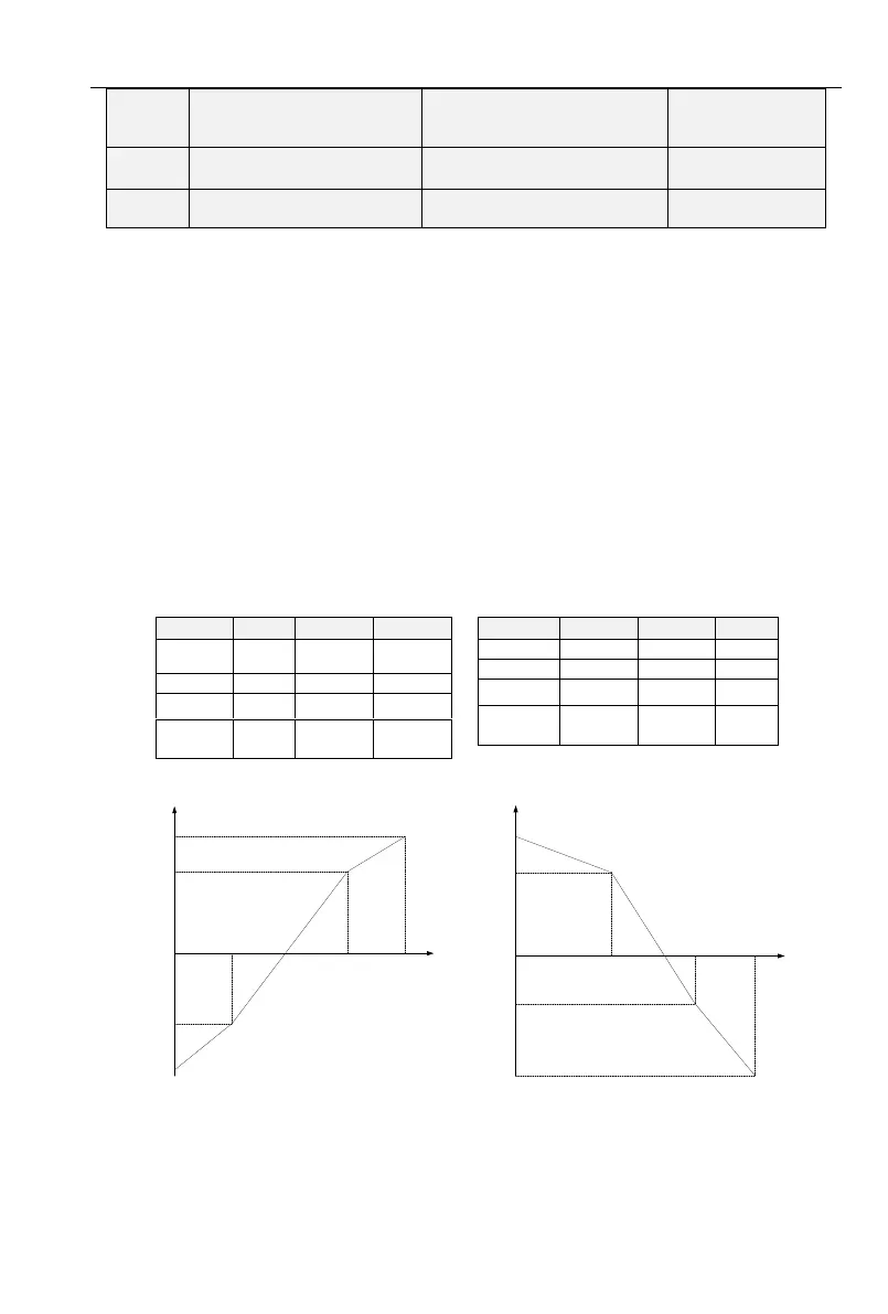
Curve diagram is shown as below:
For Instance:
Following description is taken AI1 as the example.
(1) Parameter setting
Table 6-3(1) Parameter setting 1 Table 6-3(2) Parameter setting 2
See Figure 6-17(1) and Figure 6-17(2) for input/output bias of Table 6-3(1) and Table 6-3(2)
respectively.
0.0% 25%
75%
100%
-100%
-50%
70%
100%
Fmax
7.5V 10V
C2.01
C2.03
C2.05
C2.07
C2.00 C2.02
C2.04
C2.06
2.5V
Set frequency
Analog input
0.0%
40%
75%
100%
-100%
-50%
70%
100%
Fmax
4V 7.5V
10V
C2.01
C2.03
C2.05
C2.07
C2.00
C2.02 C2.04 C2.06
Set frequency
Analog input
Fig 6-17(1) Fig 6-17(2)


 To Next Page