Emotron VS Series Quick Start Guide
- 21 -
Table 3-1 Requirement of minimum mounting clearances
3.3 Fixed manner
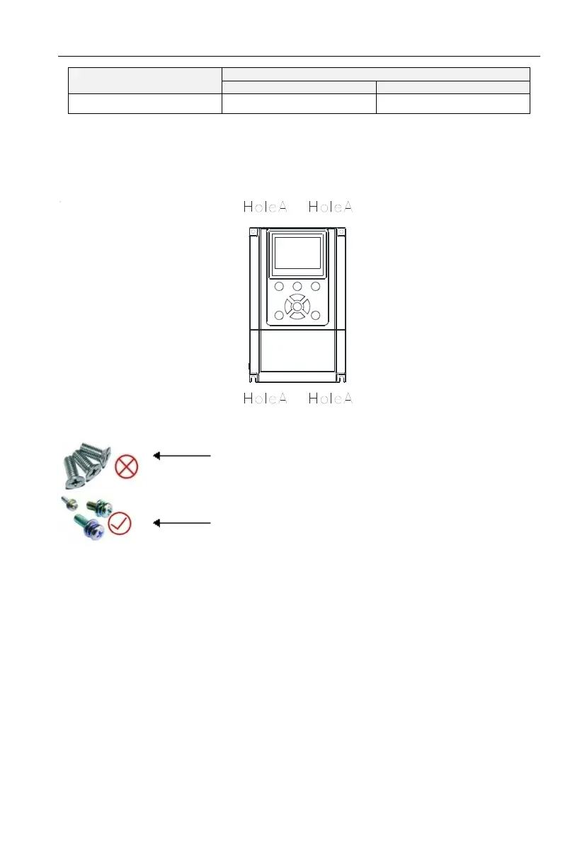
a. Wall installation
Wall mounting dimensions refer to Chapter II(table 2-3),As shown in Fig drilling four holes in
the mounting surface,Put the inverter against the panel and mate 4 holes, and then tighten screws in
the 4 holes tighten any of the 2 screws in diagonal position, tighten 4 holes with screws for
strengthened installation.
Fig 3-5 Wall mounting
Do not take the sunken screws as shown in the
picture. Otherwise, inverter may be damaged
Take screws combined with springs and plain gaskets to
Install inverter.