Emotron VS Series Quick Start Guide
- 172 -
Appendix A: Modbus Communication Protocol
1. Application Scope
1. Applicable series: CG VS series inverter.
2. Applicable network: Support Modbus protocol, RTU format, with single-master/multi-slave
Communication network of RS485 bus.
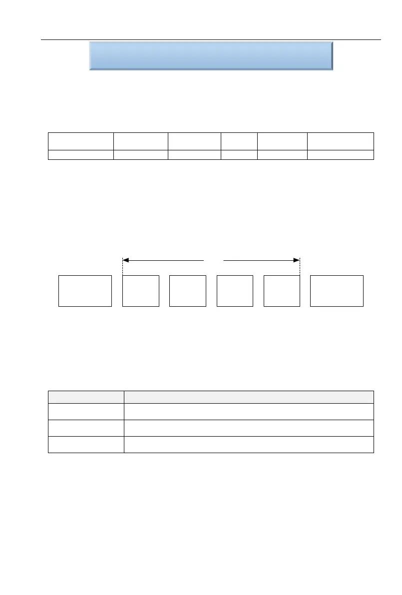
The typical RTU message frame format:
2. Physical Interface
RS485 is asynchronous half-duplex Communication mode. LSB has transmission priority.
Default data format of RS485 terminal: 1-8-N-1,bits rate: 9600bps.
Data format 1-8-N-1, 1-8-O-1, 1-8-E-1, optional bits rates 4800bps, 9600bps, 19200bps,
38400bps, 57600bps and 115200bps can be selected.
Shielded twisted-pair cable is recommended Communication cable to lower external
interference.
3. Protocol Format
Initial Block of
Frame>=Idle
Periods of 4Bits
Address of
slave
Command
Code
Data CRC
Stop Block of
Frame>=Idle
Periods of 4Bits
ADU
The parity in ADU (Application Data Unit) is obtained via the CRC16 parity of the 1st three
Parts of ADU and switch the low bytes and high bytes. Low bytes of CRC parity go first, and high
bytes of it follow in the protocol format.
4. Description of Protocol Format
4.1 Address Code
Address of slave inverter. The setting range: 1~247, 0 is broadcast address.
4.2 Command Code
Read parameters and status byte of inverter
Write single function code or control parameter of inverter
Circuit diagnosis and setting