3.0 GETTING STARTED
3-10 Cheetah Xi Programming Manual
Rev 1, 09/2013 P/N: 06-651
3.4.4 HOW TO ADDRESS DEVICES WITH THE HAND-HELD PROGRAMMER (P/N 10-2648)
The Hand-Held programmer contains the same operating code as the Cheetah Xi and can be used to assign
an address to a new addressable device. Refer to Fike document 06-390, “Hand-Held Programmer
Operating Instructions” for a complete description of the programmer’s functions and operations.
To address a device using the Hand-Held Programmer:
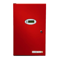
2. Turn on the Hand-Held programmer. The following Loop Start-up screen will be displayed for several
seconds. Do not make any changes to this screen.
1 2 3 4 5 6 7 8 9 0 1 2 3 4 5 6 7 8 9 0
A S ELEC T ADDRESS
B L O O P : 1 ADDRESS : 0 0 1
C W A I T F O R L O O P S T A R T :
D > > > > >>>>>>>>>>>>>>>>
Exhibit 3-14: Loop Start Screen
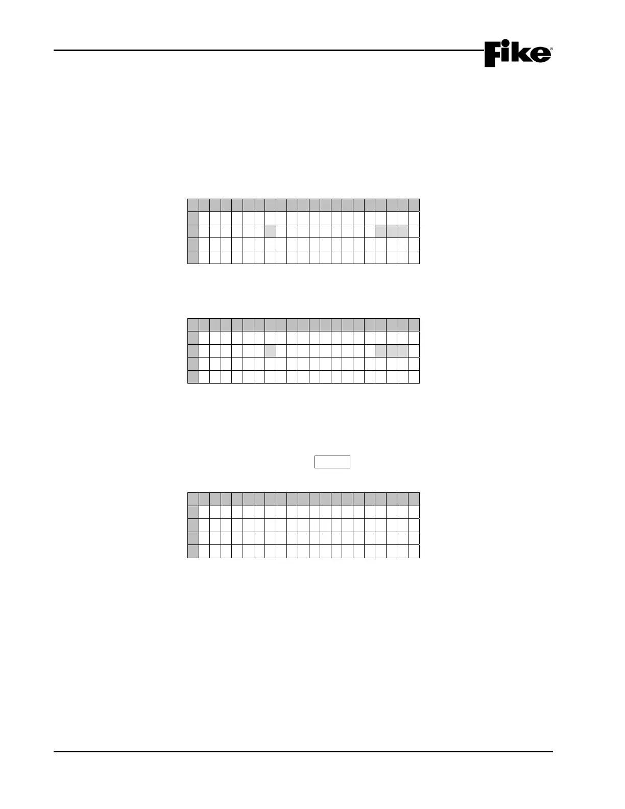
3. Upon completion of the loop start-up, the following Device Address screen will be displayed:
1 2 3 4 5 6 7 8 9 0 1 2 3 4 5 6 7 8 9 0
A S ELEC T ADDRESS
B L O O P : 1 ADDRESS : 0 0 1
C
D P R E S S E N T E R T O S T A R T
Exhibit 3-15: Device Address Screen
• Row B – Use these fields to set the loop (1 – 5) and starting address number (1 – 254) to be
assigned to the device. Use the ◄►arrow keys to move the cursor under the Loop and Address
fields; then use the +/- keys to increment/decrement the fields.
4. Once the chosen loop and address is set, press the ENTER key to start the automatic address function.
The following Connect Device screen will be displayed:
1 2 3 4 5 6 7 8 9 0 1 2 3 4 5 6 7 8 9 0
A C O N N E C T D E V I C E T O
B A D D R E S S A B L E L O O P
C P R E S S E N T E R W H E N
D C O M P L E T E
Exhibit 3-16: Connect Device Screen
• Attach sensors to the integral base on the programmer.
• Attach modules to the programmer using the supplied wire leads (Red wire to Loop positive
connection; Black wire to Loop negative connection).
 Loading...