4.0 CONFIGURATION MENU
Cheetah Xi Programming Manual 4-13
P/N: 06-651 Rev 1, 09/2013
4.2.2.1 HOW TO MODIFY NAC FUNCTIONS
The NAC Functions screen allows you to set the operational parameters of the two on-board NACs.
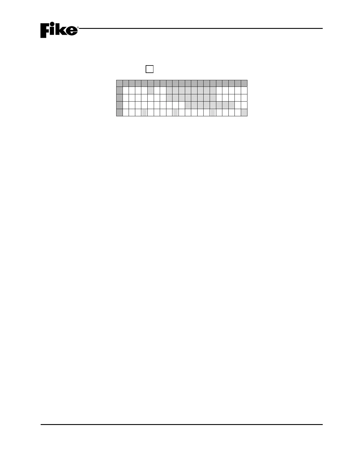
From the “NAC Menu” screen, press the F1 key to access the “NAC functions” screen, as shown below:
1 2 3 4 5 6 7 8 9 0 1 2 3 4 5 6 7 8 9 0
A
N A C # 1: E N A B L E D
B
S T A T E : S T A T E
C
P R O T O C O L : C O N S T A N T
D
S I : NDR:NWLK:NWF:Y
Exhibit 4-18: NAC Functions Screen
• Row A (NAC#) - This field allows you to select the NAC circuit to configure (NAC 1 or NAC 2). Use
the ◄► arrow keys to position the cursor under the field; then use the +/- keys to
increment/decrement the field.
• Row A (ENABLED) - This field allows you to set the Enabled/Disabled status of the on-board
notification appliance circuits 1 & 2 (P10 & P11). Use the ◄► arrow keys to move cursor under the
Enabled/Disabled field; then use the +/- keys to toggle the field.
LNote: If either NAC circuit is disabled, the panel will annunciate both a Trouble and Supervisory
condition until the circuit(s) is enabled.
• Row B (State) - This field allows you to set the operating state for the NAC circuit displayed in Row
A. Use the ◄► arrow keys to move the cursor to Row B; then use the +/- keys to change the State
to the desired operation (i.e., Alarm, Pre-Discharge, Release, Pre Alarm 1, Pre Alarm 2,
Supervisory, Trouble and Process).
• Row C (Protocol) - This field allows you to select whether the NAC circuit displayed in Row A will
use the NAC protocol set for the panel (see 4.2.2.3) or will activate constant. Use the ◄► arrow
keys to move the cursor to Row C; then use the +/- keys to change to the desired protocol.
LNote: Both NAC 1 and NAC 2 must be set to the same protocol unless one of them is set to No
Sync Protocol.
LNote: If a chime code is assigned to any zone, Row C will display ‘CHIME CODE’ by default and
can not be changed. See section 4.3.5.1 for complete description of Chime Code functionality.
• Row D - These fields allow you to set the Silenceable, Drill, Walktest and Waterflow Enabled
(Y)/Disabled (N) status for the NAC circuit displayed in Row A.
SILENCEABLE (SI:) - field determines whether or not the selected NAC circuit will turn off
when the panel’s SILENCE button is pressed.
DRILL (DR:) - field determines whether or not the selected NAC circuit will turn on when the
panel’s DRILL button is pressed.
WALKTEST (WLK:) - field determines whether or not the selected NAC circuit will turn on
when the panel receives a Walktest Alarm from any one of the configured zones.
WATERFLOW (WF:) – field determines whether or not the selected NAC circuit will turn on
when the panel receives a Waterflow Alarm.
To change the Enabled/Disabled status of these fields, use the ◄► arrow keys to position cursor
under Y or N; then use the +/- keys to toggle the field.