4-3
Manual 0-5186
OpERATION WELDSKILL 250, 350
Operation
10. VOLTAGE CONTROL SWITCH (WELDSKILL 250 ONLY)
The Voltage Control Switch is a 12 position that increases the welding voltage as it is rotated in a clockwise
direction.
CAUTION
The Voltage Control switch MUST NOT BE SWITCHED during the welding process.
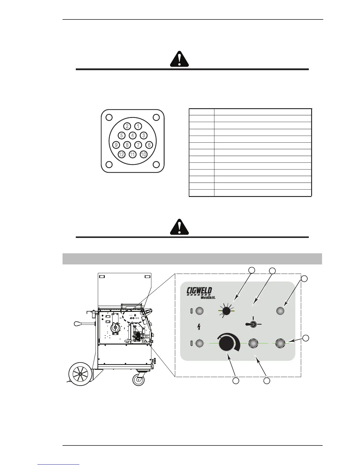
11. REMOTE SOCKET
12
345
678
101112
9
POWER SOURCE 12 PIN REMOTE SOCKET
12 PIN
1trigger
2 Motor Positive (24VDC)
3 Motor Negative
4CW of remote wirespeed pot
5ACW of remote wirespeed pot
6 wiper of 5k remote wirespeed pot
7trigger
8solenoid
9solenoid
10 no connection
11 no connection
12 no connection
Art # A-09921_AB
Figure 4-2 WeldSkill 250 & 350 MIG Remote Socket
CAUTION
The Voltage Control Switch must not be switched whilst welding.
4.02 Power Source Internal Welding Controls
Art # A-09920_AC
SPOT (s)
0
19
5
10
BURNBACK
TRIGGER
SPOT
2T
NORMAL
4T
LATCH
3A
8A
GAS PURGEINCH
15
REMOTE
LOCAL
415V
27V
A
B
C
D
E
F
Figure 4-3 Internal welding controls