Assembly Procedures 8-4 Manual 0-5186
WELDSKILL 250, 350 ASSEMBLY pROCEDURES
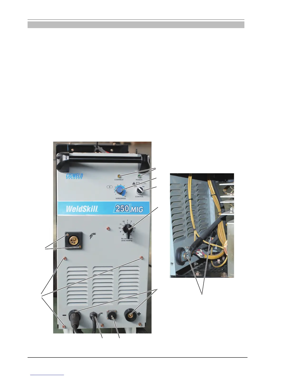
8.03 Installing Front Panel
1. Install potentiometer and knob. Align the knob pointer to line up with maximum correct calibration mark
on the panel,then set screw.
2. Install output voltage selection switch.
3. Install power and overheat indicators.
4. Output dinse ,install output dinse.
5. 4R wirefeeder connection socket. Install connection socket by screwer.
6. Torch polarity lead cable .clockwise turn anchorage until tight.
7. ON/OFF switch. Install on/off switch and reconnect input wires to switch,align the switch pointer to line
up mark on panel.
8. Install front panel screws and tighten screws.
9. Connect the output cable of rectifier assembly to output dinse.
10. Install MIG torch adaptor and cover plate.
11. Reconnect 4R wirefeeder control wires to the connector block.
1
2
9
10
7
8
Art # A-10276
3
5
6
4