4-12
Manual 0-5186
WELDSKILL 250, 350 OpERATION
Operation
Wirefeeder Connections
A. Connect the welding power cable from the Wirefeeder’s interconnection cables to the positive welding
terminal (+) [negative welding terminal (-) for flux cored electrode wire]. If in doubt, consult the elec-
trode wire manufacturer. (Power Source Torch Polarity Lead not required to be connected when using
wirefeeder)
B. Connect the control cable from the Wirefeeder to the control socket on the Power Source.
C. Fit the gas regulator and flowmeter to the gas cylinder then connect the gas hose from the rear of the
Wirefeeder to the Flowmeter outlet.
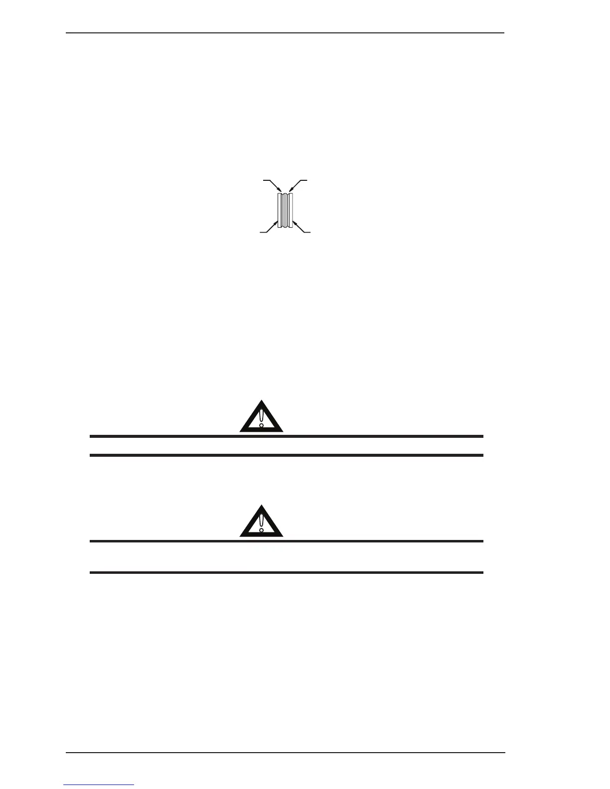
D. Dual groove feed rollers are supplied as standard. They can accommodate 0.9/1.2mm diameter hard
wires. Select the roller required with the chosen wire size marking facing outwards.
GROOVE “A” SIZE
GROOVE “B” SIZE
Art # A-08739
E. Fit the electrode wire spool to the wirefeeder wire reel hub. (Note that there is an adaptor supplied when
using 200mm diameter wire spools). Ensure that the drive dog-pin engages the mating hole in the wire
spool. Push the spool securing clip into place to retain the wire spool securely. The electrode wire should
feed from the bottom of the spool.
F. MIG Torch, EURO MIG Torch Connection
Fit the MIG Torch to the Wirefeeder by pushing the torch connector into the brass torch adaptor and
screwing the plastic torch nut clockwise to secure the torch to the torch adaptor. Remove the contact tip
from the torch handset.
Inserting Wire Into The Wire Feed Mechanism
A. Lift up the wire feeder pressure lever and pass the electrode wire through the inlet guide, between the
rollers, through the centre guide, between the rollers, through the outlet guide and into the MIG torch.
!
WARNING
DO NOT WEAR GLOVES WHILE THREADING THE WIRE OR CHANGING THE WIRE SPOOL.
B. Lower the pressure lever and with the torch lead reasonably straight, feed the electrode wire through the
torch. Fit the appropriate contact tip, eg a 0.9mm tip for 0.9mm wire.
C. Press the Torch switch to feed the wire through the torch.
!
WARNING
The electrode wire will be at welding voltage potential whilst it is being fed through the wirefeeder
system if the wire is fed by using the TORCH SWITCH.
Drive Roller Pressure Adjustment
The moveable rollers apply pressure to the grooved feed rollers via a scaled adjustable tension screw. These
devices should be adjusted to a minimum pressure that will provide satisfactory WIREFEED without slippage. If
slipping occurs, and inspection of the wire contact tip reveals no wear, distortion or burn back jam, the conduit
liner should be checked for kinks and clogging by metal flakes and swarf. If it is not the cause of slipping, the
feed roll pressures can be increased by rotating the scaled tension screws clockwise. The use of excessive
pressure may cause rapid wear of the feed rollers, shafts and bearing.