Page no. 28
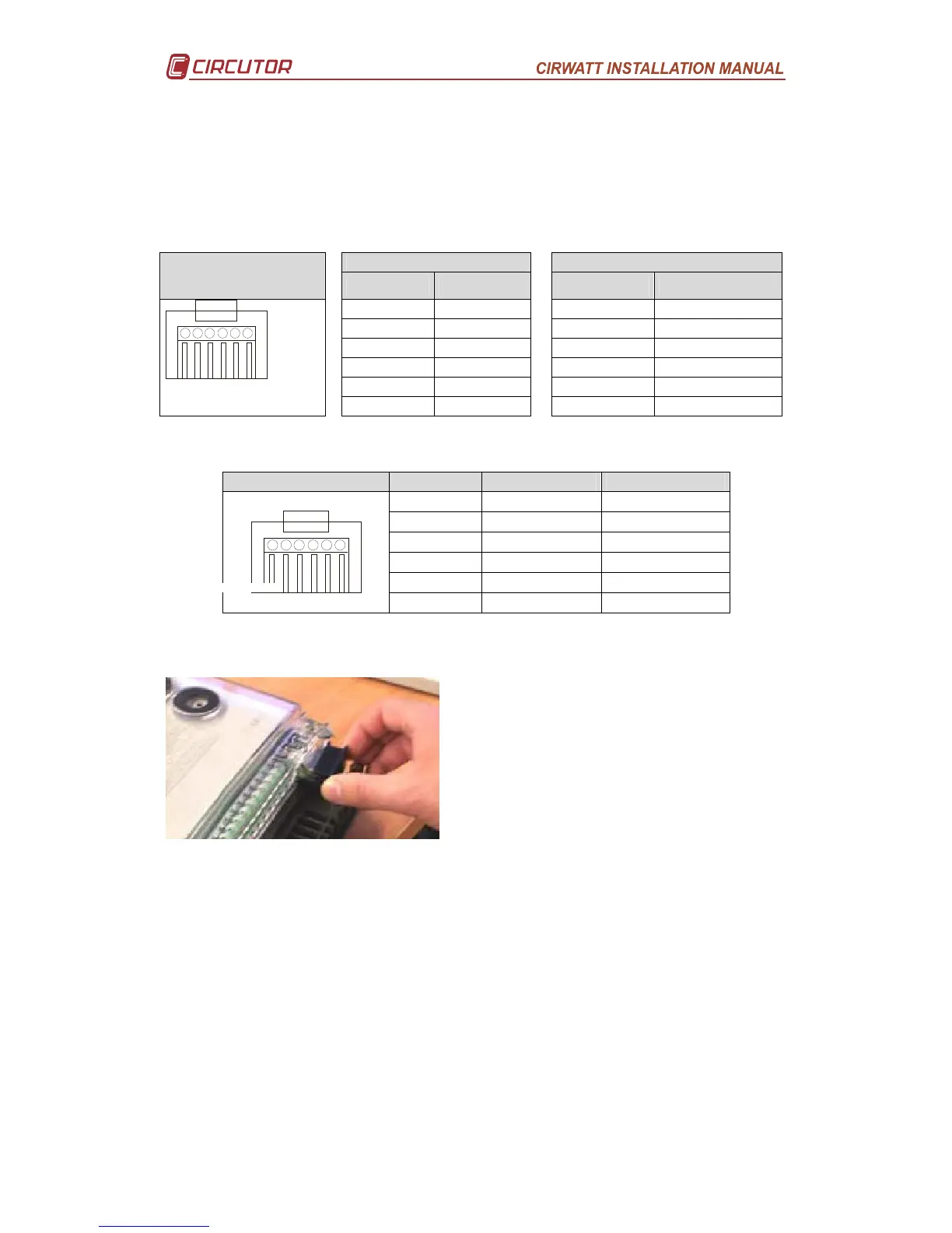
A.- CIRWATT connection diagram
It has 1 series port (Plus the optical port): R1: RS-232 or RS-485 port (according to
model: ) for on site or remote communications Reading and setting
Connection to a PC
RS-232 RS-485
RJ Cirwatt
Connector
CIRWATT P.C. (DB9)
CIRWATT Converter (DB9)
1 – GND 5 – GND 1 – GND 5 – GND
2 – RX 3 – Tx 2 –Tx/Rx (-) 2 – Tx/Rx (-)
3 – TX 2 – Rx 3–Tx/Rx (+) 1 – Tx/Rx (+)
4 –CTS 7 – CTS
5 – RTS 8 – RTS
Front view
6 – GND 5 – GND 6 – GND 5 – GND
RS-232 to external Modem.
RJ Cirwatt Connector
CIRWATT Modem (DB9) Modem (DB25)
1 – GND 5 – GND 7 – GND
2 – Rx 2 – Rx 3 – Rx
3 – Tx 3 – Tx 2 – Tx
4 – CTS 7 – CTS 5 – CTS
5 – RTS 8 – RTS 4 – RTS
1 6
2
3
4 5
6 – GND 5 – GND 7 – GND
B.- Changing the Battery
Follow the steps below to change the battery:
1. Remove the terminal cover seal”
2. Change the battery.
3. Attach terminal cover.
The battery may be changed with or without
the equipment being connected. The equipment has a SUPERCAP that keeps the
meter's clock running for 96hours, in the event of the equipment being disconnected.
The battery reference number is written on the cover that holds the battery (CR2477N)
 Loading...


