Page no. 24
6.- INSTALLATION AND START-UP
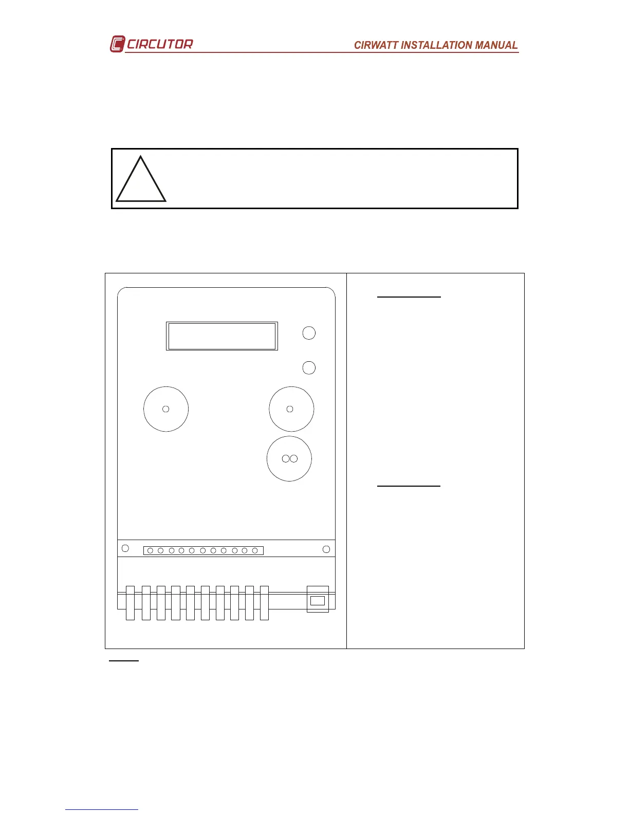
6.1.- Installing the equipment
The meter has been designed in accordance with the DIN 43857 standard defining the
sizes and the mounting points.
Remember that when the equipment is connected the terminals may be
dangerous when touched. Opening the covers or removing parts may
give access to pieces that are dangerous when touched. T
must not be used until it is fully installed.
Warning: All connections must be inside the terminal cover.
6.2.- Indirect meter terminal ratio (see label on terminal cover)
1
2
43 1165 7 8 9
R1
21 22 23 24 25 26 27 28 29 30 31
1
2
3
4
5
6
7
8
9
11
R1
21
22
23
24
25
26
27
28
29
30
31
Terminal description
Lower board
Current input IL1 – S1
Measurement UL1
Current output IL1 – S2
Current input IL2 – S1
Measurement UL2
Current output IL2 – S2
Current input IL3 – S1
Measurement UL3
Current output IL3 – S2
Neutral measurement
RS-232, RS-485 or Ethernet
Communications
Upper board
Relay output 1
Relay output 1
Relay output 2
Relay output 2
Relay output 3
Relay output 3
Input contact 1
Input contact 2
Input contact 3
Input contact 4
Input common contact
NOTE: Current inputs .. /5A or /1A are isolated.
 Loading...


