18
RGU-10A , RGU-100A
Instruction Manual
CPU
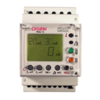
Estado / State
Figure 17: RGU-10A/RGU-100A LED indicators.
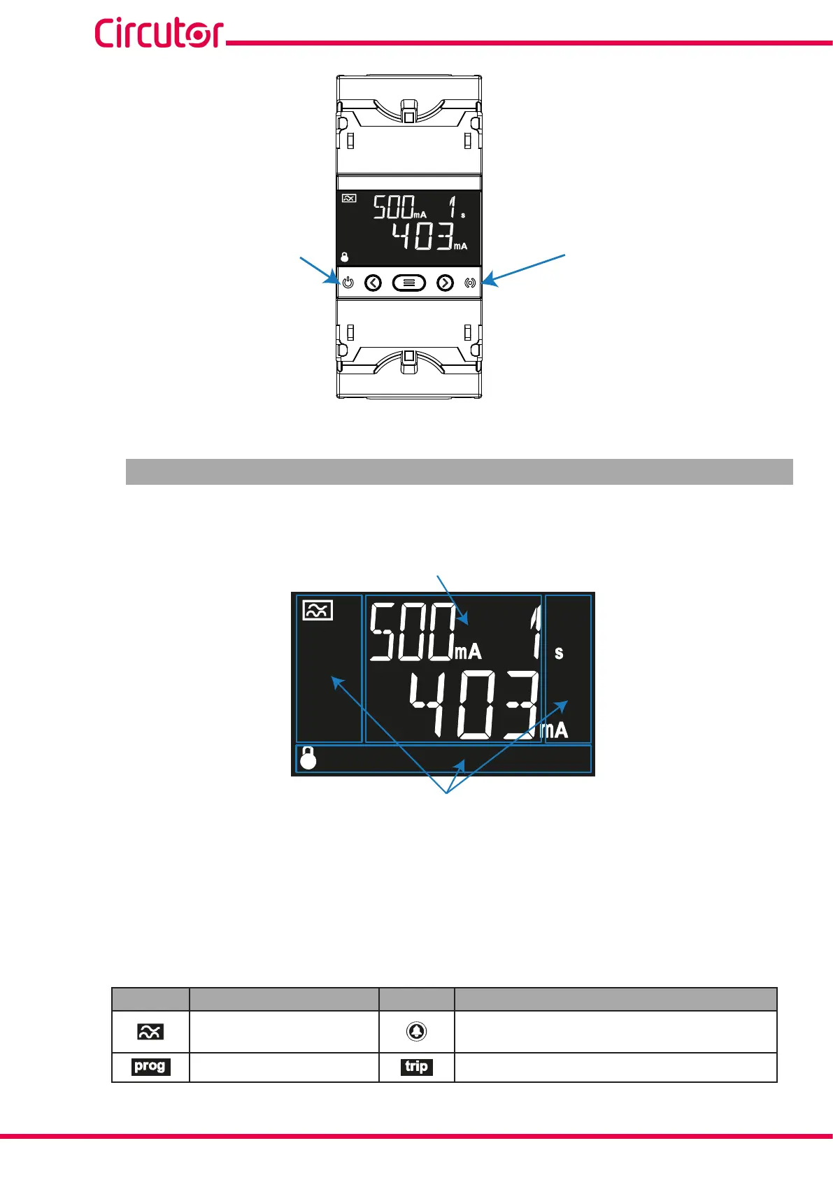
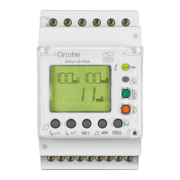
4.3 - DISPLAY
The device has a backlit LCD display that is split into two areas (Figure 18):
Unit and status areas
Data area
Figure 18: RGU-10A/RGU-100A display areas.
The data area, which displays all the values measured by the device, as well as the sensitivity
or delay settings.
The unit and device status area, which displays the different statuses, units and device in-
formation (Table 7).
Table 7: Display icons.
Icon Description Icon Description
Type-A residual current
protection
Pre-alarm activated.
Programming screen. A trip has been generated.