20
RGU-10A , RGU-100A
Instruction Manual
4.5 - RELAY
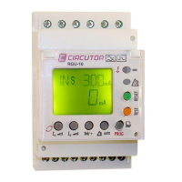
The RGU-10A /RGU-100A has 2 output relays, an R1 trip relay and an R2 pre-alarm relay (Figure 19).
See "6 - DIRECT ADJUSTMENTS" to configure the parameters of the trip relay and "7.1 - PRE-ALARM RE-
LAY" to configure the parameters of the pre-alarm relay.
Entrada digital
Digital input
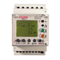
RGU-10A
19 20
94k
TRIP/RESET
230 V~
6
2 3
4
51
R2
R1
Figure 19:RGU-10A/RGU-100A relay.
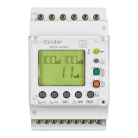
4.6 - DIGITAL INPUT
The device has a digital input, TRIP/RESET (Figure 20), to do an external trip or reset.
If this input is activated, the relay is tripped. See “5.2 - TRIP DISPLAY SCREENS”.
Entrada digital
Digital input
19 20
94k
TRIP/RESET
230 V~
Figure 20: RGU-10A/RGU-100A Digital inputs.
The TRIP/RESET digital input works like a status input, meaning if the device is in idle and a voltage
is applied to the digital input, the R1 trip relay trips. The device remains tripped while the digital input
remains activated, Figure 21.