13
Instruction Manual
RGU-10A, RGU-100A
3.5.3 DISTRIBUTION OF THE CONDUCTORS IN THE WGC
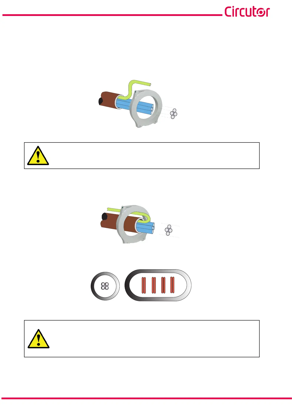
All the active conductors that feed the loads or part of the installation where earth leakage protection
or monitoring is required must pass through the WGC transformer associated with the RGU-10A /
RGU-100A.
Active conductors are defined as the phases (L1, L2 and L3) and neutral. Never the protection cable
(PE or Earth) (Figure 10).
PE
N
L
1
L
3
L
2
Figure 10:Distribution of the conductors.
Routing the Earth cable (PE) and the rest of the active conductors through the
transformer disables earth leakage current measurement, and earth leakage
protection and motorisation consequently cease to function.
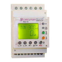
In the event of having to route a cable hose containing all the conductors, including the earth con-
ductor (PE), the PE conductor must be routed in the opposite direction to counteract the effects of its
original path, see Figure 10.
N
L
1
L
3
L
2
PE
Figure 11:Conductor distribution (cable hose).
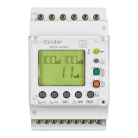
Conductor routing must be neat, centred and separated from the transformer’s inner opening, Figure 12.
L1
L3
L2
N
Figure 12:Correct distribution of conductors.
The inadequate arrangement of the conductors, as shown in Figure 13, as well as not
following the recommendations indicated in Figure 14, can cause the transformer
to lose its measurement efficiency and residual current protection. Unexpected
disconnections may occur in the installation if the WGC is associated to a differential
relay that actuates the circuit breaker.