9
Instruction Manual
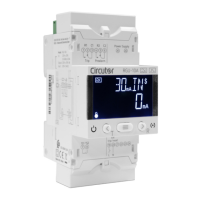
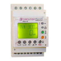
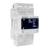
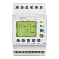
RGU-10A, RGU-100A
1
2
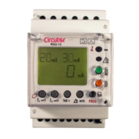
Figure 1:Installing the RGU-10A on the DIN rail.
The device has a LED (CPU) that indicates voltage presence. Even if the aforemen-
tioned LED is off, the user still needs to verify that the device is disconnected from
any power supply.
The RGU-10A /RGU-100A has to be connected to a power circuit that is protected with a circuit-break-
er or equivalent device to disconnect the device from the mains supply.
3.3 - PANEL MOUNTING ACCESSORY (72 x 72 mm)
Note: The 72 x 72 mm panel mounting accessory is sold separately.
CIRCUTOR has a panel mounting accessory for the RGU-10A /RGU-100A device so that it can be in-
stalled on 72 x 72 mm panels.
Figure 2 shows the installation of the panel mounting accessory to the RGU-10A /RGU-100A.
Disconnect all power supplies and measuring equipment from the device before in-
stalling the panel mounting accessory.
Figure 2: Installation of the panel mounting accessory.