3-67
Cisco Aironet 1552 Series for Hazardous Locations Installation Guide
Chapter 3 Installing the 1552 Series Access Points in Hazardous Locations
Installation Details for the 1552SA and 1552SD Access Point
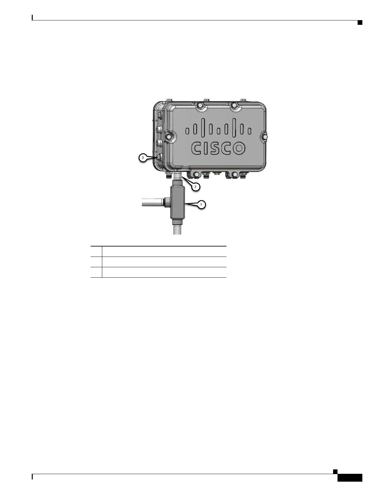
Step 5 Attach the junction box to the chassis with a 1/2 NTP Male to Male connector. See Figure 3-16 and
Figure 3-17.
Figure 3-16 ERT50 Junction Box Assembly
Step 6
Route the power cable and the fiber cable through the junction box using Figure 3-17 as an example.
1 ERT50 Junction Box
2 AC/DC Port
3 5/8-24 Port