Step 5 Press the phone firmly into the wall bracket and slide the phone down. The tabs in the bracket click into
position.
Step 6 Proceed to Adjust the Handset Rest, on page 505.
Remove the Phone from the Non-Lockable Wall Mount
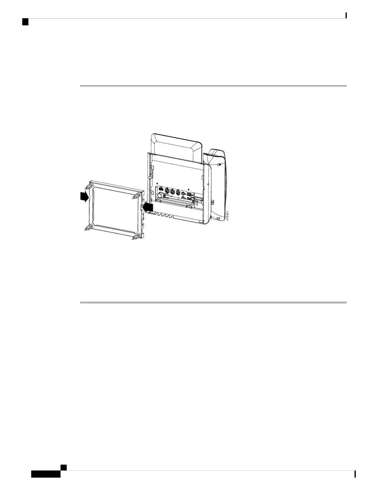
The wall bracket has two tabs that lock the kit together. Use the following illustration to locate the tabs.
Figure 15: Tab Location
Before you begin
Obtain two Phillips head screwdrivers or other similar devices that have a diameter of 5 millimeters or 3/16ths
of an inch.
Procedure
Step 1 Insert a screw driver or other device into the left and right holes in the phone mounting plate. Insert to a depth
of about 3/4 of an inch or 2 centimeters.
Step 2 Press firmly inwards to disengage the tabs.
Cisco IP Phone 8800 Series Multiplatform Phone Administration Guide for Release 11.3(1) and Later
498
Cisco IP Phone Accessories
Remove the Phone from the Non-Lockable Wall Mount

 Loading...