4-23
Cisco ASR 1000 Series Aggregation Services Routers Hardware Installation and Initial Configuration Guide
OL-13208-03
Chapter 4 Cisco ASR 1006 Router Overview and Installation
Connecting Power to Cisco ASR 1006 Router
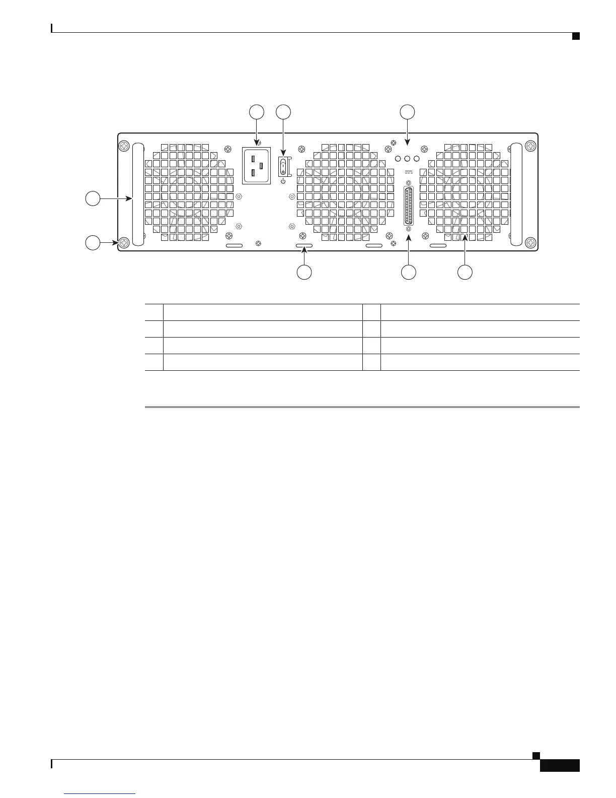
Figure 4-14 Cisco ASR 1006 Router AC Power Supply Power Inlet and Standby Switch
Step 3 Plug the AC power supply cable into the AC power source.
This completes the procedure for connecting AC-input power.
Connecting DC-Input Power to Cisco ASR 1006 Router
This section describes how to connect the DC power supply into the Cisco ASR 1006 Router.
Before you begin, read these important notices:
• The color coding of the DC-input power supply leads depends on the color coding of the DC power
source at your site. Typically, green or green/yellow is used for ground (GND), black is used for
-48V on negative (–) terminal and red is used for RTN on the positive (+) terminal. Make certain the
lead color coding you choose for the DC-input power supply matches lead color coding used at the
DC power source.
• For DC input power cables, select the appropriate wire gauge based on the National Electrical
Code
(NEC) and local codes for 40-amp service at nominal DC input voltage (–48/–60 VDC).
Three
pairs of cable leads, source DC (–) and source DC return (+), are required for each power
distribution unit (PDU). These
cables are available from any commercial cable vendor. All input
power cables for the chassis should have the same wire gauge and cable lengths should match within
10 percent of deviation.
Each DC input power cable is terminated at the PDU by a cable lug. The cable lugs must be
dual-hole, and have a straight tongue. They must be able to fit over 1/4-inch terminal studs at
0.625-inch (15.88-mm) centers.
1 AC power supply fan 5 AC power supply handle
2 DB-25 alarm connector 6 AC power inlet
3 Tie-wrap tab 7 AC power supply Standby switch
4 AC power supply captive screw 8 AC power supply LEDs
280029
OUTPUT INPUT INPUT
FAIL OK OK
ALARMS
60V
1A MAX
100-240V~ 16-7A
50-60HZ
This unit might have more than
one power supply connection.
All connections must be removed
to de-energize the unit.
2 13
4
5
6 7
8

 Loading...


