5-25
Cisco ASR 1000 Series Aggregation Services Routers Hardware Installation and Initial Configuration Guide
OL-13208-03
Chapter 5 Cisco ASR 1004 Router Overview and Installation
Connecting Power to Cisco ASR 1004 Router
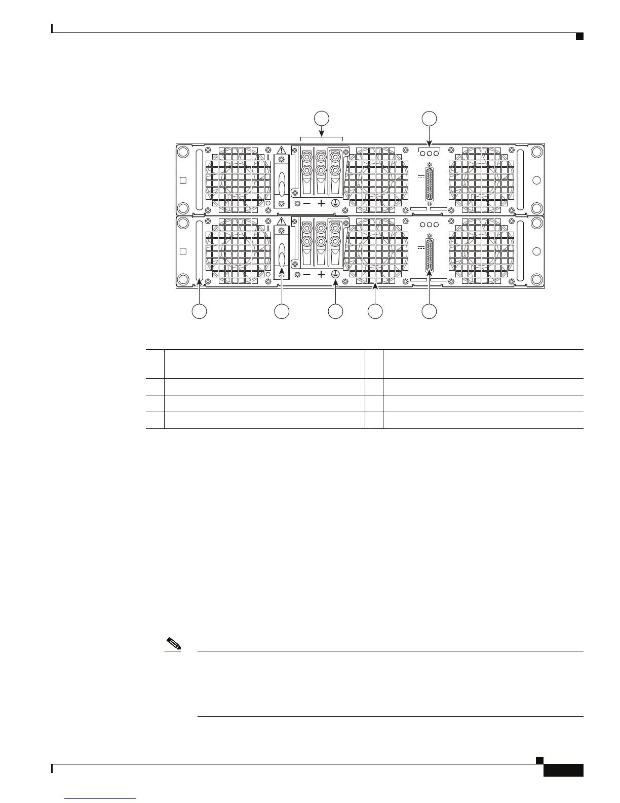
Figure 5-17 Cisco ASR 1004 Router DC Power Supply
Before you begin, read these important notices:
• The color coding of the DC-input power supply leads depends on the color coding of the DC power
source at your site. Typically, green or green/yellow is used for ground (GND), black is used for
-48V on negative (–) terminal and red is used for RTN on the positive (+) terminal. Make certain the
lead color coding you choose for the DC-input power supply matches lead color coding used at the
DC power source.
• For DC input power cables, select the appropriate wire gauge based on the National Electrical
Code
(NEC) and local codes for 60-amp service at nominal DC input voltage (–48/–60 VDC).
Three
pairs of cable leads, source DC (–) and source DC return (+), are required for each power
distribution unit (PDU). These
cables are available from any commercial cable vendor. All input
power cables for the chassis should have the same wire gauge and cable lengths should match within
10 percent of deviation.
Each DC input power cable is terminated at the PDU by a cable lug. The cable lugs must be
dual-hole, and have a 45-degree angle tongue. They must be able to fit over #10 power terminal stud.
Note DC input power cables must be connected to the PDU terminal studs in the proper positive
(+) and negative (–) polarity. In some cases, the DC cable leads are labeled, which is a
relatively safe indication of the polarity. However, you must verify the polarity by measuring
the voltage between the DC cable leads. When making the measurement, the positive (+)
lead and the negative (–) lead must always match the (+) and (–) labels on the PDU.
280185
OUTPUT INPUT
FAIL
OK OK
FAN
60V
1A MAX
OUTPUT INPUT
FAIL
OK OK
FAN
60V
1A MAX
1
2
345
67
1 DC power supply terminal block and plastic
cover
5 DC power supply earth ground symbol
2 DC power supply LEDs 6 DC power supply On (I)/ Off (O)
3 DB-25 alarm connector 7 DC power supply handle
4 DC power supply fan

 Loading...


