EasyManuals Logo

Cisco Catalyst 9200 Series Hardware Installation Guide

Cisco Catalyst 9200 Series
128 pages
To Next Page IconTo Next Page
To Previous Page IconTo Previous Page
Page #61 background imageLoading...
Page #61 background image
Three 8-18 Phillips pan-head screws
Two 10-32 Phillips pan-head screws
Screwdriver
Procedure
Step 1 Place the mounting tray on to the mounting surface.
Step 2 Use a 0.144-in. (3.7 mm) or a #27 drill bit to drill three holes, 1/2-inches (12.7 mm) deep in the desk.
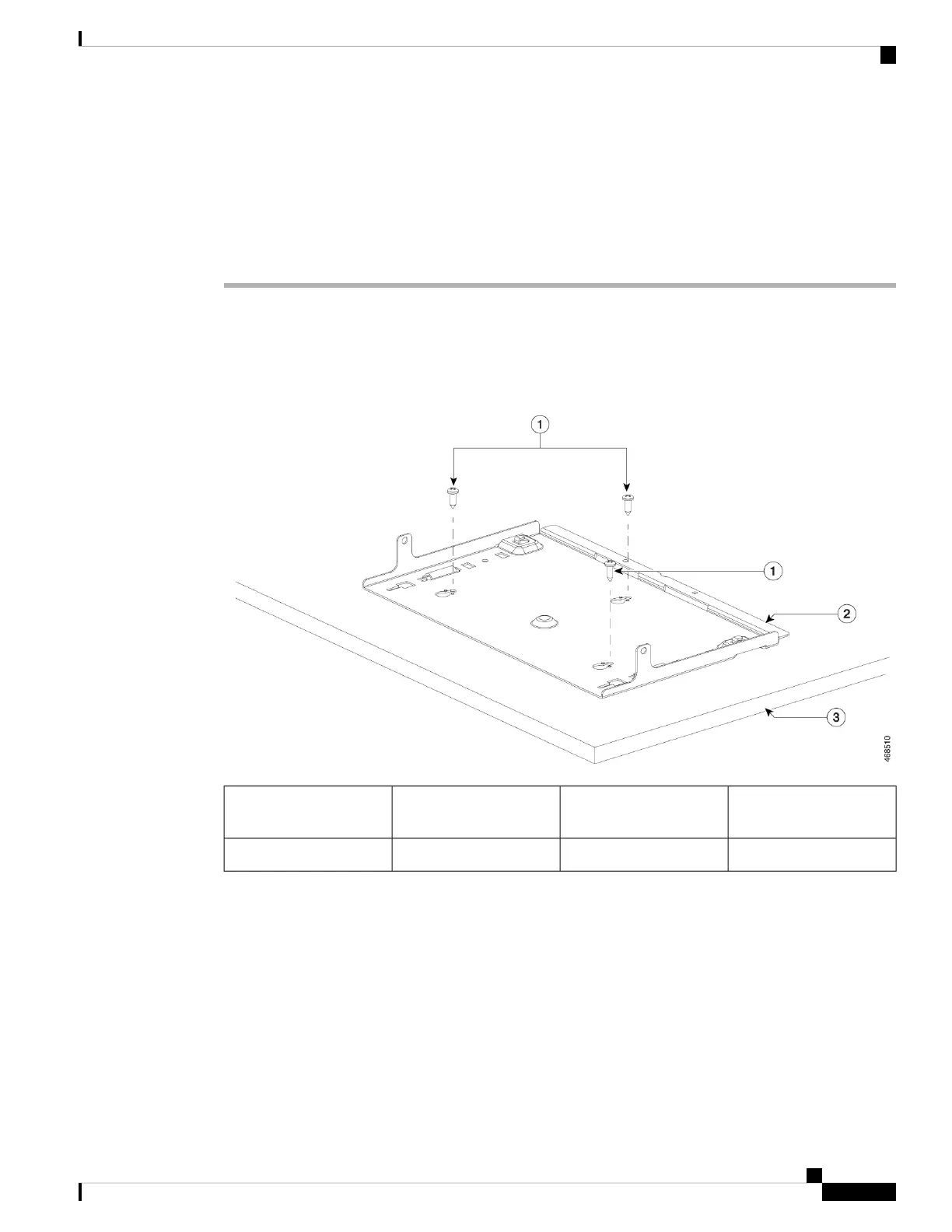
Step 3 Insert the three 8-18 Phillips pan-head screws in to the slots on the mounting tray, and tighten them.
Figure 23: Attaching the Mounting Tray to the Desk or Shelf
Desk3Three 8-18 Phillips
pan-head screws
1
--Mounting tray2
Step 4 Place the switch on the mounting tray, slide it slightly forward so that the mounting tray hooks on both the
sides engage with the switch.
Cisco Catalyst 9200 Series Switches Hardware Installation Guide
53
Installing a Compact Switch
Mounting using the Mounting Tray and Screws

Table of Contents

Other manuals for Cisco Catalyst 9200 Series

Questions and Answers:

Question and Answer IconNeed help?

Do you have a question about the Cisco Catalyst 9200 Series and is the answer not in the manual?

Cisco Catalyst 9200 Series Specifications

General IconGeneral
CategorySwitch
Stacking Bandwidth160 Gbps
LayerLayer 2 and Layer 3
Operating SystemCisco IOS XE
Operating Temperature0°C to 45°C (32°F to 113°F)
SeriesCisco Catalyst 9200 Series
Ports24 or 48 Ethernet ports
Switching CapacityUp to 176 Gbps
PoEPoE, PoE+, and UPOE
StackingStackWise-160
Memory4 GB DRAM, 4 GB Flash
Network ManagementCisco DNA Center, WebUI, CLI
Security Features802.1X, TrustSec, MACsec
WarrantyLimited Lifetime Warranty
Dimensions1.73 x 17.5 x 11.3 in. (4.4 x 44.5 x 28.8 cm)

Related product manuals