54 Tempest®900 4-Channel Wireless Intercom System
2-Wire Wiring Schemes
Wiring schemes vary, and it is important to ensure that the cables are wired correctly for proper system operaon. When
Tempest is congured for a parcular manufacturer’s system, Tempest routes the signal to internal circuitry that conforms
to the requirements of that system. The 3-pin XLR connectors on the back of the Tempest BaseStaon can have very
dierent characteriscs depending on the seng of the slide switch, as can be seen in the table below.
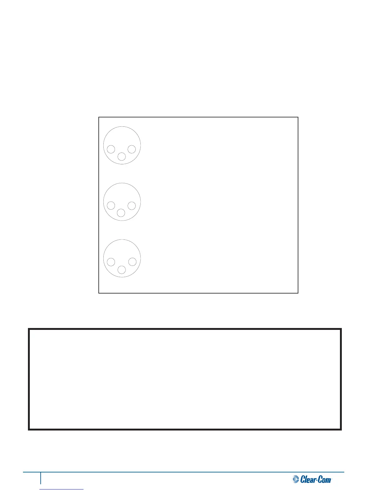
3-Pin Wiring Scheme and Line Characteriscs
1 2
1
1
2
2
3
Clear-Com
AudioCom
RTS
1 COMMON
2 POWER
3 AUDIO
1 COMMON
2 AUDIO(-) & POWER
3 AUDIO(+) & POWER
1 COMMON
2 AUDIO 1 & POWER
3 AUDIO 2
MALE
MALE
MALE
Input Impedance 200Ω
Output Level 1.0 Vrms
Bridging Impedance >10 kΩ
Call Signaling:
Send 12 ±3 VDC
Receive 4 VDC Min
Power voltage 30.0 VDC
Input Impedance 300Ω
Output Level 1.0 Vrms
Bridging Impedance >10 kΩ
Call Signaling:
Send 20 kHz ±100 Hz, 5 mVrms
Receive 20 kHz ±800 Hz, 100 mVrms
Power voltage 24.0 VDC
Input Impedance 200Ω
Output Level 0.775 Vrms
Bridging Impedance >10kΩ
Call Signaling:
Send 20 kHz ±100 hz, 240 mVrms
Receive 20 kHz ±800 Hz, 100 mVrms
Power voltage 28.0 VDC
3
3
Note for 2-Wire RTS Users: RTS TW (2-Wire) systems support two intercom channels on a single XLR cable. When connecng
an RTS TW system, only one cable is required for two intercom channels. When set to RTS mode, both of the 3-PIN XLR
connectors (2 male and 2 female) for channels A&B and C&D are paralleled together. RTS intercom channel 1 is placed on
Tempest intercom channel A, and RTS channel 2 is placed on channel B.; RTS intercom channel 1 is placed on channel C and
RTS channel 2 is placed on channel D.
Note for 2-Wire Clear-Com and Balanced (Audiocom) Users: For Clear-Com and Balanced 2-Wire intercoms, use the A, B, C,
and D male or female 3-pin (XLR-3M/F) connectors on the rear panel to connect up to four intercom channels. The male and
female connectors for each channel are loop-through connecons and are the same point electrically. Each channel of a Clear-
Com or Balanced 2-Wire system requires one separate cable for connecon to one Tempest channel.

 Loading...