STEERINGANDFRONTSUSPENSIONLiftedFrontSuspensionComponents
7
3.Removethewheel.
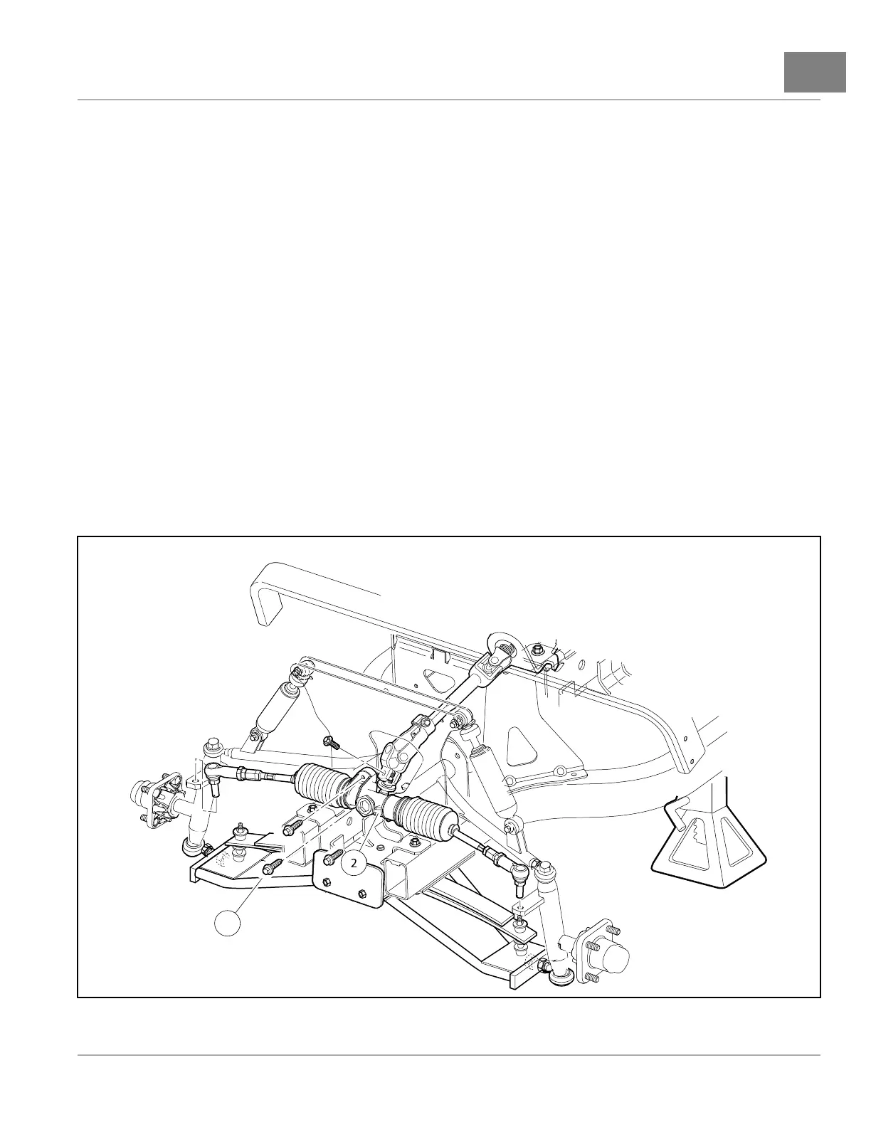
4.Removebolts(1)andmoverackandpinion(2)toallowclearanceforthebolt(3)(Figure7-23,Page7-23)
and(Figure7-24,Page7-24).
5.Removethebolt(4)andtaperedwasher(5)fromthetopofthespindle(6)(Figure7-24,Page7-24).
6.Removethenut(7)andbolt(8).
7.Removethebolt(3).
8.Removethecontrolarm(9).
LIFTEDCONTROLARMINSTALLATION
1.Installthecontrolarminreverseorderofremoval.Tightenthecontrolarmbolt(3)to30lb·ft(41N·m)(Figure
7-24,Page7-24).
2.Tightentherodend(10)to81lb·ft(110N·m)(Figure7-24,Page7-24).
3.Tightenthreerackandpinionmountingbolts(1)to22lb·ft(30N·m)(Figure7-23,Page7-23).
4.Tightentheshockabsorberbolt(8)to29lb·ft(39N·m)(Figure7-24,Page7-24).
5.Tightenthespindlebolt(4)to118lb·ft(160N·m)(Figure7-24,Page7-24).
6.Installthewheelsandadjustthewheelalignmentasinstructedonpage7-6.
7.ElectricVehicle:Connectbatteries.SeeConnectingtheBatteries–ElectricVehicles,Section1,Page1-4.
GasolineVehicle:Connectbatteryandsparkplugwire(s).SeeConnectingtheBattery-GasolineVehicles
onpage1-3.
Figure7-23LiftedSuspensionRackandPinion
2018OnwardMaintenanceandServiceManualPage7-23
 Loading...