Electrical installation and wiring
98-127093-H Chapter 5: Installation 5-33
5555
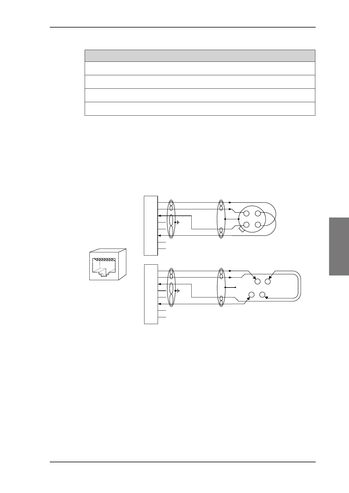
Wiring of RJ45 connector to Quadrax connector
The physical layer conforms to IEEE standard 802.3 [1], Chapter 14: “Twisted Pair medium
attachment unit”, except for the connector type. To be compliant with [1], use an RJ45
female connector for the user interface. The below drawing shows the corresponding RJ45
connection. The SBU is configured as Data communication Equipment (DCE), i.e. TX +/- are
input and RX +/- are outputs.
Figure 5-20: Ethernet pin configuration for SBU
Common Signal GND (BP15, BP17, BP21, BP22 and BP27)
Common Signal GND is used to connect the shield of the Ethernet cables for Ethernet #4,
#5 and #6 on the SBU. The shield for each cable is connected according to Figure 5-
19: Wiring Ethernet. The shield of the Ethernet cables for Ethernet #1, #2 and #3 is
connected to the shield of the Quadrax connectors.
BP26 Rx+ 10/100BaseT Ethernet #5 Output 3 RxD+
BP27 Common Signal GND for Ethernet GND Shield
BP28 Tx+ 10/100BaseT Ethernet #6 Input 1 TxD+
BP29 Rx+ 10/100BaseT Ethernet #6 Output 3 RxD+
SBU pin Name Description RJ45 pin (F) Name
Table 5-17: SBU Pins for 10/100BaseT Ethernet (Continued)
6%8SLQ
73$$$
6KLHOG
7[' 7;LQSXW
QF
7['
7; LQSXW
5['
5;RXWSXW
QF
5['
5; RXWSXW
QF
QF
2KP
TXDGUD[WZLVWHG
DQGVKLHOGHGSDLUV
7[' 7;LQSXW
QF
7['
7; LQSXW
5['
5;RXWSXW
QF
5['
5; RXWSXW
QF
QF
DQGVKLHOGHGSDLUV
6%8SLQ
6%8'&(
%3 %3
%3
5-
IHPDOH
WR'7(
%3
%3
&DEOH
&DEOH
2KP
TXDGUD[WZLVWHG
SB-Lite.book Page 33 Tuesday, September 5, 2017 1:38 PM
 Loading...