Home
COBHAM
Conference System
AVIATOR 200
COBHAM AVIATOR 200 Installation Manual
4
of 1
of 1 rating
309 pages
Give review
Manual
Specs
To Next Page
To Next Page
To Previous Page
To Previous Page
Loading...
Troubleshooting
98-127093-H
Chapter 7: Maintenance and troubleshooting
7-13
7777
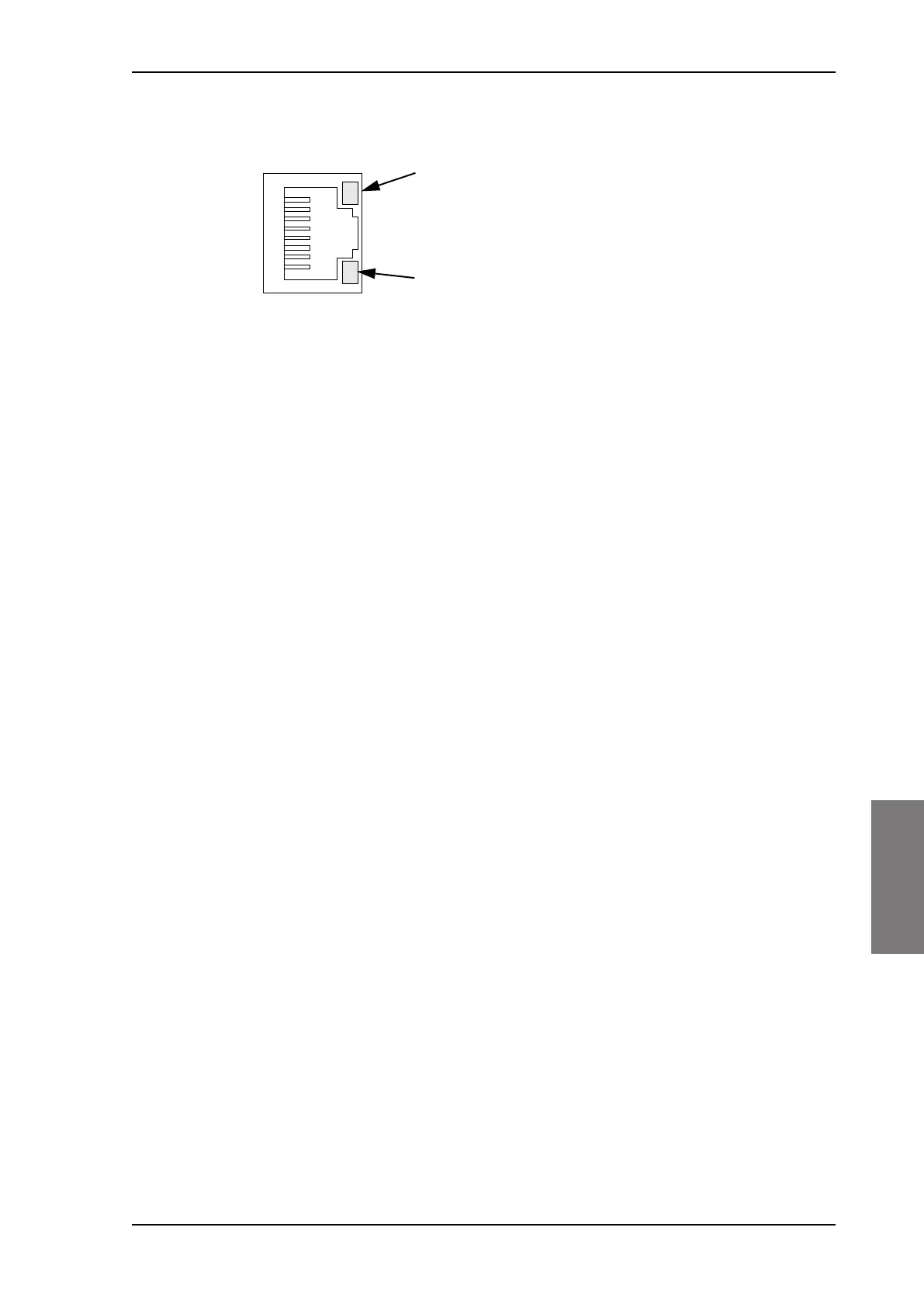
LEDs on maintenance connector
Figure 7-8:
F
unction of the LEDs on the front maintenance connec
tor
LED Flashing yellow
Activity (data in/out)
LED Steady green
Link (correct connection)
SB-Lite.book Page 13 Tuesday, September 5, 2017 1:38 PM
236
238
Table of Contents
Default Chapter
5
A-1
5
Table of Contents
7
Chapter 1 About this Manual
21
Purpose
21
Organization
21
Related Documentation
22
Precautions: Warnings, Cautions and Notes
22
Table 1-1: List of Related Documentation
22
Chapter 2 Introduction to the AVIATOR
23
General Description
23
The AVIATOR 200/300/350 System
23
Figure 2-1: Communication Devices for the AVIATOR 200/300/350 System (Example for a Level E System)
24
Table 2-1: Swiftbroadband Services for Supported Antenna Types
25
Table 2-2: Satcom Antenna Types for the AVIATOR 200/300/350 System
26
Table 2-3: Priorities for SATVOICE Calls (SB-Safety Voice)
28
AVIATOR 200/300/350 Features
29
Table 2-4: Available Features for Software Versions (Level D)
30
Application
31
Minimum System
31
Part Numbers
31
Table 2-5: Part Numbers
31
Table 2-6: Part Numbers for Configuration Modules and Options
32
Table 2-7: Part Numbers for Klixon Circuit Breaker
33
Applicable External Units
34
Table 2-8: Part Number for Connector
34
Table 2-9: Installation Kits, Contact Information
34
Table 2-10: Basic Installation Kits from ECS for the SBU
34
Table 2-11: List of Applicable External Units
34
System Block Diagrams
36
AVIATOR 200 System with LGA-3000 Antenna
36
Figure 2-2: System Configuration with LGA-3000 Antenna
36
AVIATOR 300 System with TT-5006A IGA Antenna
37
Figure 2-3: System Configuration with TT-5006A IGA Antenna
37
AVIATOR 350 System with Cobham Antennas
38
Figure 2-4: System Configuration with Cobham Antennas
38
AVIATOR 350 System with ARINC-741/781 Antennas
39
Figure 2-5: System Configuration ARINC 429 Antennas
39
AVIATOR 350D System with ACARS Option and ARINC-741/781 Ant
40
Figure 2-6: System Configuration ARINC 429 Antennas
40
User Interfaces
41
Figure 2-7: AVIATOR 200/300/350 Interfaces
41
Table 2-12: AVIATOR 200/300/350 User Interfaces
41
Chapter 3 Equipment Drawings
43
Introduction
43
Tt-5040A Sbu
44
Figure 3-1: Outline Drawing: TT-5040A SBU
44
TT-5040A-001 CM (Inserted in the SBU)
45
Figure 3-2: Outline Drawing: TT-5040A-001 CM, Inserted in the SBU
45
TT-5038A-003 Rx Power Splitter
46
Figure 3-3: Outline Drawing: Rx Power Splitter
46
Tt-5016A Hld
47
Figure 3-4: Outline Drawing: TT-5016A HLD
47
Tt-3002A Lga
48
Figure 3-5: Outline Drawing: TT-3002A LGA
48
Tt-5006A Iga
49
Figure 3-6: Outline Drawing: TT-5006A IGA Antenna
49
TT-5621B 2-Wire Handset
50
Figure 3-7: Outline Drawing: TT-5621B 2-Wire Handset
50
TT-5622B 2-Wire Cradle
51
Figure 3-8: Outline Drawing: TT-5622B 2-Wire Cradle
51
SBU Trays
52
Figure 3-9: Outline Drawing: SBU Tray: ECS PO299-101
52
Figure 3-10: Outline Drawing: SBU Tray: EMTEQ MT4-2346-101
53
Figure 3-11: Outline Drawing: SBU Tray: EMTEQ MT4-2346-101
54
SBU Tray Connector
55
Figure 3-12: Outline Drawing: SBU Tray Connector: ITT Cannon DPX2NA-67322-606
55
Contact Assembly: Quadrax Pin Size 5 Special
56
Figure 3-13: Contact Assembly: Quadrax Pin Size 5 Special: ITT Cannon 244-0011-001
56
Figure 3-14: Outline Drawing: TT-5040A-004 WLAN Antenna
58
TT-5040A-004 WLAN Antenna
58
Figure 3-15: Outline Drawing: Switch Annunciator Panel
59
Switch Annunciator Panel
59
Chapter 4 Connectors and Pin-Out
61
Tt-5040A Sbu
61
Connectors on SBU
61
SBU Maintenance Connector
61
Figure 4-1: SBU Maintenance Connector, Face View of Engaging End
61
Table 4-1: Pin-Out for SBU Maintenance Connector (Standard Ethernet)
62
SBU Rear Receptacle
63
Figure 4-2: SBU Rear Receptacle, Engaging End (Index Code: 19)
63
Figure 4-3: SBU Rear Receptacle with Pin Functions
64
Table 4-2: Pin-Out for SBU Rear Receptacle, Top Plug
67
Table 4-3: Pin-Out for SBU Rear Receptacle, Bottom Plug
68
Tt-5016A Hld
69
Connectors on HLD
69
Figure 4-4: TT-5016A HLD Connector Panel
69
TT-5622B 2-Wire Cradle
70
Connectors on 2-Wire Cradle
70
Figure 4-5: 2-Wire Cradle Connectors, End View of Cradle
70
Figure 4-6: TT-5622B 2-Wire Cradle Connectors, Side View of Cradle
70
2-Wire Cradle Connector to SBU
71
Figure 4-7: 2-Wire Cradle Connector (DB9M). View: Solder Side
71
Table 4-4: Pin-Out for 9 Pin Sub-D Male Connector in TT-5622B 2-Wire Cradle
71
Mating Connectors in Aircraft
72
Connection with SBU
72
Table 4-5: Mating Connectors in Aircraft for SBU
72
Chapter 5 Installation
73
General Installation Information
73
Overview
73
Table 5-1: Installation Kits, Contact Information
73
Minimum System Components
74
Figure 5-1: AVIATOR 200 Minimum System (Example with LGA TT-3002A and GPS Antenna)
74
Mounting Considerations
75
Overview
75
Tt-5040A Sbu
75
Tt-5016A Hld
75
Satcom Antenna
76
Table 5-2: Navigational Input for Satcom Antennas
76
TT-5040A-004 WLAN Antennas
79
Figure 5-2: Mounting Two WLAN Antennas for Optimum Performance
79
Electrical Installation and Wiring
80
Table 5-3: Wiring Symbols
80
Wiring Symbols
80
Figure 5-3: Wiring SBU Power Supply
81
Table 5-4: Pins for SBU Power Supply
81
Wiring Power Supply
81
Table 5-5: Requirements to SBU Power Cables
82
Wiring the Satcom Antenna
82
Figure 5-4: Wiring TT-3002A LGA/LGA-3000
83
Figure 5-5: Wiring TT-5006A IGA or IGA-5001
84
Figure 5-6: Wiring HGA-6000
85
Figure 5-7: Wiring HGA-6500 Antenna (Variation 2, Label at Antenna Plug: 1 and 2)
86
Figure 5-8: Wiring HGA-6500 Antenna (Variation 3 Label at Antenna Plug: y and S)
87
Figure 5-9: Wiring HGA-7001
88
Figure 5-10: Wiring HGA-7001 with AIS 380 Aircraft Interface Module
89
Figure 5-11: Wiring AMT-50
90
Figure 5-12: Wiring AMT-700
91
Figure 5-13: Wiring AMT-3500/3800
92
Figure 5-14: Wiring IGA-5001. HGA-7000 and HGA-8000
93
Figure 5-15: Wiring CMA-2102/CMA-2102SB
94
Table 5-6: SBU Pins for Satcom Antenna System
95
Table 5-7: HLD Connectors for Satcom Antenna System
95
Figure 5-16: Wiring ARINC 429 Navigational Input
97
Table 5-10: SBU Pins for Input from a Navigational ARINC 429 Source
97
Wiring ARINC 429 Interfaces
97
Table 5-11: ARINC Data Format for IRS
98
Table 5-12: ARINC Data Format for AHRS
98
Table 5-13: ARINC Data Format for NPI
99
Table 5-14: ARINC Data Format for GNSS
99
Figure 5-17: Wiring the CMU
100
Table 5-15: SBU Pins for Input from GPS Antenna
100
Figure 5-18: Wiring GPS Interface with Power Splitter
101
Wiring GPS Interface
101
Table 5-16: SBU Pins for Input from GPS Antenna
102
Figure 5-19: Wiring Ethernet
103
Wiring Ethernet
103
Table 5-17: SBU Pins for 10/100Baset Ethernet
104
Figure 5-20: Ethernet Pin Configuration for SBU
105
Figure 5-21: Wiring WLAN Antenna Interfaces #1 and #2
106
Table 5-18: SBU Pins for WLAN Antenna #1 and #2
106
Wiring WLAN Antenna Interface
106
Table 5-19: WLAN Antenna Configuration
107
Table 5-20: Cable Requirements for WLAN
107
Table 5-21: Low Pass Filter for WLAN, Order Information
107
Figure 5-22: Wiring ISDN Interface
108
Table 5-22: SBU Pins for ISDN
108
Wiring ISDN
108
Figure 5-23: ISDN RJ45 Connector
109
Wiring Telephone Systems
109
Figure 5-24: Handset Interfaces with Possible Combinations of Connected Devices
111
Figure 5-25: Wiring T&T 2-Wire Handset Systems
111
Table 5-23: SBU Pins for 2-Wire Interface
111
Wiring Sigma 7 (2-Wire) Handsets
112
Figure 5-27: Wiring ICG DECT Cordless Handset Handsets
113
Wiring ICG DECT Cordless Handset (2-Wire) Phone
113
Figure 5-28: Wiring Discretes
114
Table 5-24: SBU Pins for Discrete Annunciators
114
Wiring Discretes
114
Table 5-25: SBU Pin for Chime/Lamps Inhibit Input
115
Table 5-26: SBU Pins for Discrete Inputs
115
Figure 5-29: Wiring the Switch Annunciator Panel MD-41-1948
116
Table 5-27: Specification of Discrete Types
116
Wiring the Switch Annunciator Panel
116
Table 5-28: SBU Pins for Discrete Inputs
117
Wiring an SB-Safety Voice Annunciator Panel
117
Wiring the Maintenance Interface
117
Figure 5-30: Wiring Maintenance PC and Reset
118
Table 5-29: SBU Pins for Maintenance Interface
118
Introduction
119
Power Cables, Allowed Cable Lengths
119
Recommended Cables
119
Table 5-30: Allowed Lengths for SBU Power Cables
119
Recommended Power Cables
120
Recommended RF Cables
120
Table 5-31: Allowed Lengths for HLD Chassis Ground Cable
120
Table 5-32: List of Recommended RF Cables
120
Recommended Cables for ARINC 429
121
Recommended Cables for Ethernet
121
Table 5-33: Allowed Lengths for WLAN Cables
121
Activation of Airtime Services
122
Cables for Discrete Signals
122
Chapter 6 Configuration of the AVIATOR 200/300/350 System
125
Figure 6-1: Line of Sight When Communicating with the Satellite
125
Basic Configuration of the SBU
126
Configuration Tasks
126
Tool for Setup and Use: Built-In Web Interface
130
Check the Connection to the Web Interface
131
Figure 6-9: Topics in the Web Interface
131
Topics in the Web Interface
131
Figure 6-10: Sections of the Web Interface (Example for AVIATOR 350)
132
Table 6-1: Web Interface: Icons
133
Figure 6-11: Web Interface: Dashboard (Example: AVIATOR 350)
136
Overview
136
Properties
136
The Dashboard
136
View Information on Calls and Data Sessions
137
Figure 6-12: Web Interface: Start a Data Connection
138
Profiles on the Dashboard
138
Figure 6-13: Web Interface: Phone Book, Mobile Numbers (Example, no Multi-Voice)
139
General Usage
139
The Phone Book
139
View and Edit the Mobile and Additional Numbers
139
Figure 6-14: Web Interface: Phone Book, Mobile Numbers (Example, with Multi-Voice)
140
To Set up the Interfaces
141
The SETTINGS Page
141
Select the Preferred BGAN Satellite
142
Figure 6-15: Web Interface: Settings, Satellite Selection
142
Configure the LAN Interface
143
Figure 6-16: SBU IP Addresses: Local and Global IP Addresses, Default
143
Figure 6-17: Web Interface: Settings, LAN
144
Figure 6-18: Web Interface: Settings, LAN, Port Forwarding
145
WLAN Interface (Option)
146
Figure 6-19: Web Interface: Settings, WLAN (Example: AVIATOR 350)
146
Configure the Phone/Fax Interface (2-Wire)
148
Figure 6-20: Web Interface: Settings, Phone/Fax
148
Configure the ISDN Interface
149
Figure 6-21: Web Interface: Settings, ISDN
149
Set the Common Interface Settings
151
Figure 6-22: Web Interface: Settings, Common
151
Set up Call Services
152
Figure 6-23: Web Interface: Settings, Common, Call Forward
153
Figure 6-24: Web Interface: Settings, Common, Call Barring
154
Figure 6-25: Web Interface: Settings, Common, Call Waiting
155
Figure 6-26: Web Interface: Settings, Common, Line Identification
156
Figure 6-27: Web Interface: Settings, Common, Closed User Group
157
Manage AVIATOR Wireless Handsets
158
Figure 6-28: Web Interface: Settings, IP Handsets
159
Figure 6-29: Web Interface: Settings, IP Handsets, Call Settings
160
Configure the Discrete I/O Interfaces
161
Figure 6-30: Web Interface: Settings, Discrete I/O (Without SB-Safety Voice)
162
Set the System Type
163
Figure 6-31: Web Interface: Settings, Discrete I/O (with SB-Safety Voice)
163
Figure 6-32: Web Interface: Settings, System Type
164
Table 6-2: Changing the System Type, Use of Reset Button
165
Configure RF Settings
167
Figure 6-33: Web Interface: Settings, RF Settings
167
Set up the Navigational Input
168
Table 6-3: Navigational Input for System Types and Satcom Antennas
168
Figure 6-34: Web Interface: Settings, External Systems (AVIATOR 350 with TT-5006 Antenna)
169
Calibrate the NRS Magnetometer in the TT-5006A IGA
170
Figure 6-35: Web Interface: Settings, External Systems, Magnetometer Calibration
171
Table 6-4: Evaluation of the Magnetometer Calibration Score
172
Table 6-5: Magnetometer Calibration: Error Messages at Failing Start Procedure
174
Table 6-6: Magnetometer Calibration: Error Messages at Failing Stop Procedure
174
Set up CMU/ACARS (Option)
175
Table 6-7: Satcom Antennas in AVIATOR Systems Supporting CMU
175
Figure 6-36: Web Interface: CMU/ACARS
176
Enable System Options with FLEX Keys
177
Figure 6-37: Web Interface: Settings, FLEX (Example)
177
Tracking
178
Figure 6-38: Web Interface, Settings, Tracking
178
SB-Safety Voice (Option)
179
LAN/WLAN Network Users
181
Introduction
181
Figure 6-42: Overview over Network User Groups and Traffic Flow Filters
181
Set up the Network User Groups
183
Figure 6-43: Web Interface: Settings, LAN, Network User Groups
183
Figure 6-44: Web Interface: Settings, LAN, Network User Groups, Edit
184
Manage Network Devices
186
Figure 6-45: Web Interface: Settings, LAN, Network Devices
186
The Network Classification Table
187
Figure 6-46: Web Interface: Settings, LAN, Network Classification Table
188
Figure 6-47: Web Interface: Settings, LAN, Network Classification Table, Edit or Add
188
Definitions for Network Terms
189
Figure 6-48: Web Interface: Settings, LAN, Network Classification Table, Change Priority
189
NAT (Network Address Translation)
190
Start and Stop any Data Session
190
Figure 6-49: NAT (Network Address Translation)
190
Figure 6-50: Web Interface: Connect, to Start and Stop Data Sessions (Example)
190
Establish a Pppoe Connection
191
Figure 6-51: Example for Pppoe Connections
191
Figure 6-52: Web Interface, Settings, LAN, Pppoe
192
Table 6-8: Pppoe Connection, Service Names and Descriptions
193
Table 6-9: Pppoe Connection, Service Names and Descriptions for Custom APN
193
To Set up Static Routing
194
Figure 6-53: Web Interface, Settings, LAN, Static Route
194
Figure 6-54: Web Interface, Settings, LAN, Static Route, Add
194
SNMP Interface
195
Administration
195
Protect the SBU against Unintended Configuration Changes
195
Access the Administration Settings
196
Figure 6-55: Web Interface: Administration
196
Figure 6-56: Web Interface: Administration, Change Administrator Logon
197
Figure 6-57: Web Interface: Administration, Reset Administrator Password
198
Save and Load a Configuration
199
Figure 6-58: Web Interface: Administration, Saving a Configuration File
199
Figure 6-59: Web Interface: Administration, Saving a Configuration File
200
Call Charges
201
Figure 6-60: Web Interface: Administration, Call Charges
201
Log Handling
202
Data Limits
202
To Use Profiles
202
Figure 6-61: Web Interface: Administration, Log Handling
202
Figure 6-62: Web Interface, Administration, Profiles, Example: Standard
203
Figure 6-63: Web Interface. Administration, Profiles, Select Profile (Example AVIATOR 350)
204
To Use Traffic Flow Filters
206
Figure 6-64: Traffic Flow Filters to Filter Traffic Types
206
Figure 6-65: Web Interface: Administration, Traffic Flow Filters
207
Figure 6-66: Web Interface: Administration, Traffic Flow Filters, New Entry
207
Figure 6-67: Web Interface: Example of Two Traffic Flow Filters
208
SIM Card Access Protection: SIM PIN and SIM Lock
209
Figure 6-68: Web Interface, Administration, SIM PIN
209
Figure 6-69: Web Interface, Administration, SIM LOCK
210
Set up User Permissions
211
Figure 6-70: Web Interface: Administration, User Permissions
211
Remote Management
213
Figure 6-71: Web Interface: Administration, Remote Management
213
Remote Activation of a Connection Using SMS
214
Link Monitoring (Swiftbroadband Only)
214
Figure 6-72: Web Interface: Administration, Link Monitoring
214
Restricted Dialing
215
Multi-Voice (Option)
215
Table 6-10: Multi-Voice, Number of Calls
215
Figure 6-73: Multi-Voice, Call Type Groups (Example)
217
Figure 6-74: Multi-Voice, Example of Directly Assigned Handsets (Example)
217
Figure 6-75: Multi-Voice, Example of Unassigned Handsets
218
Figure 6-76: Multi-Voice, Example for a Configuration with Cockpit Reserve
218
Figure 6-77: Web Interface: Administration, Multi-Voice
219
Figure 6-78: Web Interface: Phone Book, Mobile Numbers (Example, Multi-Voice)
220
Figure 6-79: Web Interface: Settings, IP Handsets, Call Settings (with Multi-Voice, Example)
221
Site Map
222
Figure 6-80: Web Interface: Site Map
222
Configuration of 3Rd Party Phone Systems
223
Sigma 7 Setup
223
ICG DECT Cordless Handset Setup
223
AVIATOR 200/300/350 System Ready for Use
224
Figure 6-81: AVIATOR 200/300/350 System
224
Chapter 7 Maintenance and Troubleshooting
225
Continued Airworthiness
225
General
225
Instructions
225
Get Support: HELPDESK
227
Airtime Support
227
System Support
227
Help Desk and Diagnostic Report
227
Figure 7-1: Web Interface: Help Desk
227
Figure 7-2: Web Interface: Help Desk, Extended Status
228
Software Update
229
SBU Software Update
230
Figure 7-3: Web Interface: Settings, Upload
231
Verify the Software Update
232
Figure 7-4: Software Identification on the SBU Label, Level D and Level E
232
To Exchange Lrus
233
Time Consumption
233
Tools
233
Removal and Re-Installation of the SBU
233
Figure 7-5: Exchanging an LRU (Example)
233
Figure 7-6: Pull out the LRU
234
Figure 7-7: Attach CM to the Airframe
234
Troubleshooting
235
Status Signalling
235
Status Signalling with Leds
236
Table 7-1: Function of the SBU Power LED
236
Table 7-2: Function of the SBU Logon LED
236
Table 7-3: Function of the SBU Fail/Pass LED
236
Figure 7-8: Function of the Leds on the Front Maintenance Connector
237
IP Reset (Default) Button
238
Figure 7-9: IP Reset (Default) Button on SBU Front
238
Table 7-4: How to Reset the IP Address or the Terminal Software to Default Settings
239
View the Event List, Event Log and Extended Status
240
Figure 7-10: Web Interface: Help Desk, Event List
240
Self Test
241
Figure 7-11: Web Interface: Help Desk, Self Test
241
Initial Troubleshooting
242
Table 7-5: Initial Troubleshooting
242
Return Units for Repair
243
Disposal of Electrical and Electronic Equipment
244
Appendices
245
Appendix A Equipment Specifications
247
Introduction
247
AVIATOR 200/300/350 System Components
248
TT-5040A Swiftbroadband Unit (SBU
248
Table A-1: Equipment Specifications for TT-5040A SBU
248
TT-5040A-001 Configuration Module (CM) for SBU
249
Table A-2: Equipment Specifications for TT-5040A-001 CM
249
TT-5016A High Power Amp./Low Noise Amplifier/Diplexer (HLD
250
Table A-3: Equipment Specifications for TT-5016A HLD
250
TT-5040A-004 WLAN Antenna
251
TT-5038A-003 Rx Power Splitter
251
Table A-4: Equipment Specifications for WLAN Antenna
251
Table A-5: General Specifications for Rx Power Splitter
251
AVIATOR 200/300/350 Handsets and Cradles
253
TT-5621B 2-Wire Handset
253
TT-5622B 2-Wire Cradle
253
Table A-6: Equipment Specifications for 2-Wire Handset
253
Table A-7: Equipment Specifications for 2-Wire Cradle
253
Appendix B DO-160 Specifications
255
General
255
Certifying Agency
255
Environmental Qualification Forms
255
AVIATOR 200/300/350 System Components
256
Swiftbroadband Unit (SBU
256
Table B-1: Environmental Qualification Form for SBU
256
Configuration Module (CM) for SBU
258
High Power Amplifier/Low Noise Amplifier/Diplexer (HLD
258
Table B-2: Environmental Qualification Form for HLD
258
Rx Power Splitter
260
Table B-3: RTCA/DO-160D Change Numbers, Tx Coupler and Rx Power Splitter
260
Table B-4: Environmental Qualification Form for Tx Coupler and Rx Power Splitter
260
AVIATOR 200/300/350 Handsets and Cradles
262
2-Wire Handset and 2-Wire Cradle
262
Table B-5: Environmental Qualification Form for 2-Wire Handset and Cradle
262
Appendix C System Messages
265
Types of Messages
265
List of Events
266
Table C-1: SBU Events
266
Restrictions in WLAN Use
277
Countries Where the "US" Country Code Applies
278
Table D-1: Countries that Accept the Country Code "US" for WLAN Indoor Operation
278
Appendix D WLAN Country Codes
279
Appendix E References
279
Applicable Standards
279
E.1 Applicable Standards
279
Appendix F TT-5019A Iridium Band Reject Filter
281
Introduction
281
System Block Diagram
281
Figure F-1: System Configuration with TT-5019A Iridium Band Reject Filter (1
281
F.1 Introduction
281
Equipment Drawing
282
Figure F-2: Outline Drawing: TT-5019A Iridium Band Reject Filter
282
F.2 Equipment Drawing
282
Installation
283
Mounting Considerations
283
Figure F-3: Wiring TT-5019A Iridium Band Reject Filter
283
F.3 Installation
283
Electrical Installation and Wiring
284
Configuration
284
Specifications
284
Table F-1: Distance to Iridium
284
Table F-2: Equipment Specifications for TT-5019A Iridium Band Reject Filter
284
Table F-3: Environmental Qualification Form for Iridium Band Reject Filter
285
F.6 DO-160 Specifications
285
Appendix G Terminal Commands
287
Get Started
287
Connect to the SBU
287
G.1 Get Started
287
Commands for Troubleshooting the SBU
288
Monitor the ARINC Interfaces on the SBU
288
Description of the Status Report
289
Table G-1: Status ARINC Driver, Overview
290
Table G-2: Purpose of the States for Receivers
290
Table G-3: Purpose of the States for the Antenna Modem
290
Table G-4: Status for All Mandatory Labels on the Interface in Question
291
Table G-5: Status ARINC Driver: Source
291
Table G-6: Receiver: Header Line for the Table
291
Table G-7: Status for Label Types
292
Introduction
293
Connect to the WLAN Interface
293
Set up a SIP Profile
293
H.1 Introduction
293
Appendix H SIP Setup for Wifi-Enabled Phones
295
Glossary
295
Index
299
Other manuals for COBHAM AVIATOR 200
User Manual
136 pages
4
Based on 1 rating
Ask a question
Give review
Questions and Answers:
Need help?
Do you have a question about the COBHAM AVIATOR 200 and is the answer not in the manual?
Ask a question
COBHAM AVIATOR 200 Specifications
General
Brand
COBHAM
Model
AVIATOR 200
Category
Conference System
Language
English
Related product manuals
COBHAM AVIATOR 300
136 pages
COBHAM AVIATOR UAV 200
61 pages
COBHAM FliteLine CVC-151
36 pages
 Loading...