Electrical installation and wiring
5-34 Chapter 5: Installation 98-127093-H
5.3.7 Wiring WLAN antenna interface
Before wiring the WLAN antenna interface make sure that your system has the Built-in
Wireless Option TT-5040A-003.
With software 4.00 and SB-Safety voice the WLAN access point must be
disabled in the configuration software.
Overview
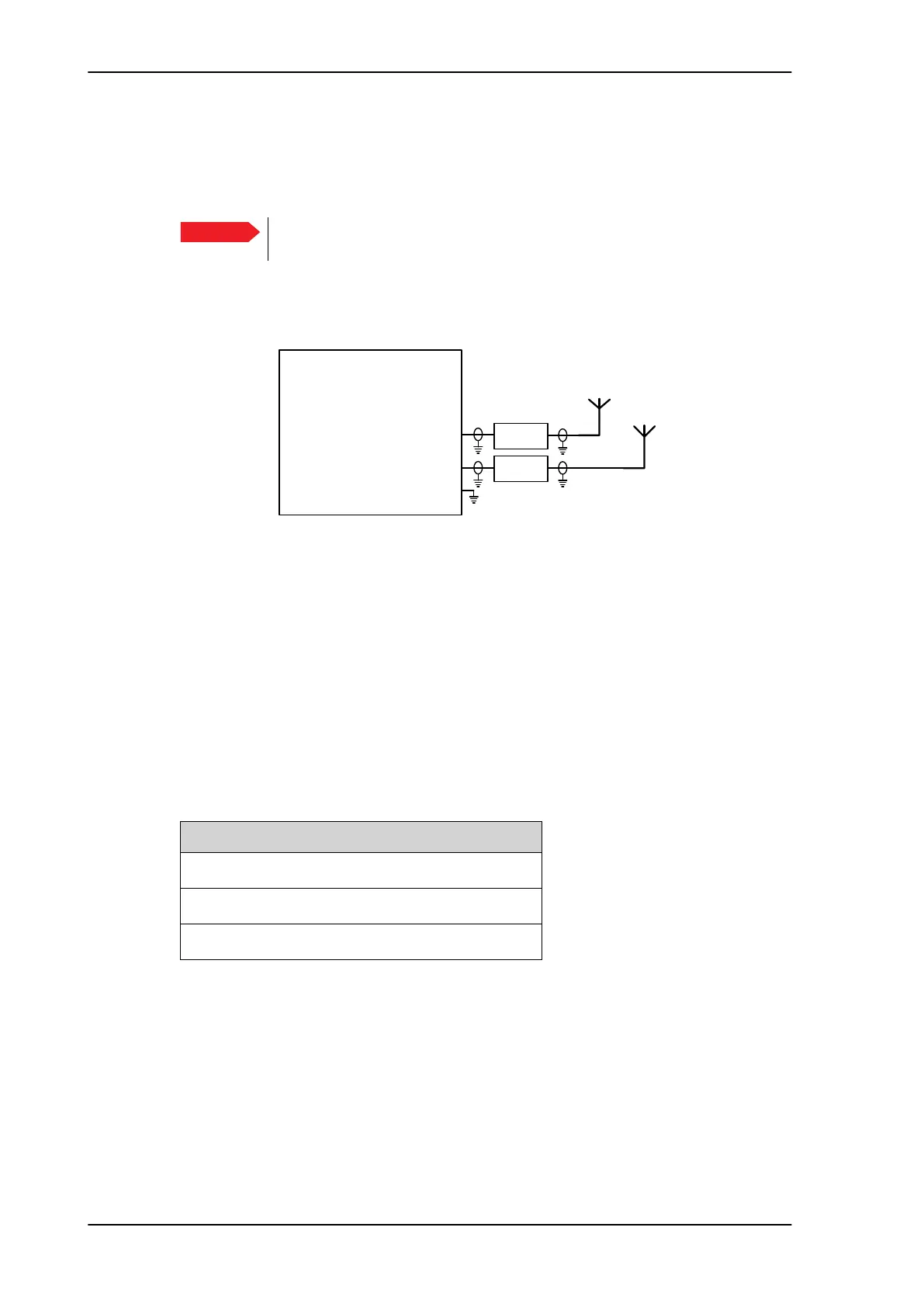
The following drawing shows the wiring of the SBU WLAN antenna interfaces.
Figure 5-21: Wiring WLAN antenna interfaces #1 and #2
WLAN low pass filter
The WLAN module in the SBU can in theory transmit in the 5 GHz (802.11a) frequency
range. This is inhibited permanently by the software in the SBU. If the aircraft cannot be
tested to be immune to 5 GHz signals, you can optionally insert a 2.4 GHz low pass filter
into the WLAN Coax to safeguard the aircraft against transmission in the 5 GHz frequency
range.
WLAN pins
The following list shows the pins used for the WLAN antenna interface on the SBU.
Important
77$
6%8
:/$1DQWHQQDFRD[73$
:/$1DQWHQQDFRD[73$
73
:/$1HQDEOH
:/$1DQWHQQDDQG
:
:
/RZ3DVV
)LOWHU>@
/RZ3DVV
)LOWHU>@
>@2SWLRQDO
SBU pin Name/description
TPA2 WLAN antenna #1 (coax)
TPA4 WLAN antenna #2 (coax)
TP5 WLAN Enable, Discrete Input (active low)
Table 5-18: SBU pins for WLAN antenna #1 and #2
SB-Lite.book Page 34 Tuesday, September 5, 2017 1:38 PM
 Loading...