D-MBR 3707-3708 PS NFPA CLASS A SIGNAL BOOSTER
PRODUCT DESCRIPTION AND USER’S MANUAL
www.cobham.com/wireless
Date: 17-Jan-16
Cobham Wireless – Coverage
Page | 26 Rev. 1.1 Doc. No.00060CDUM
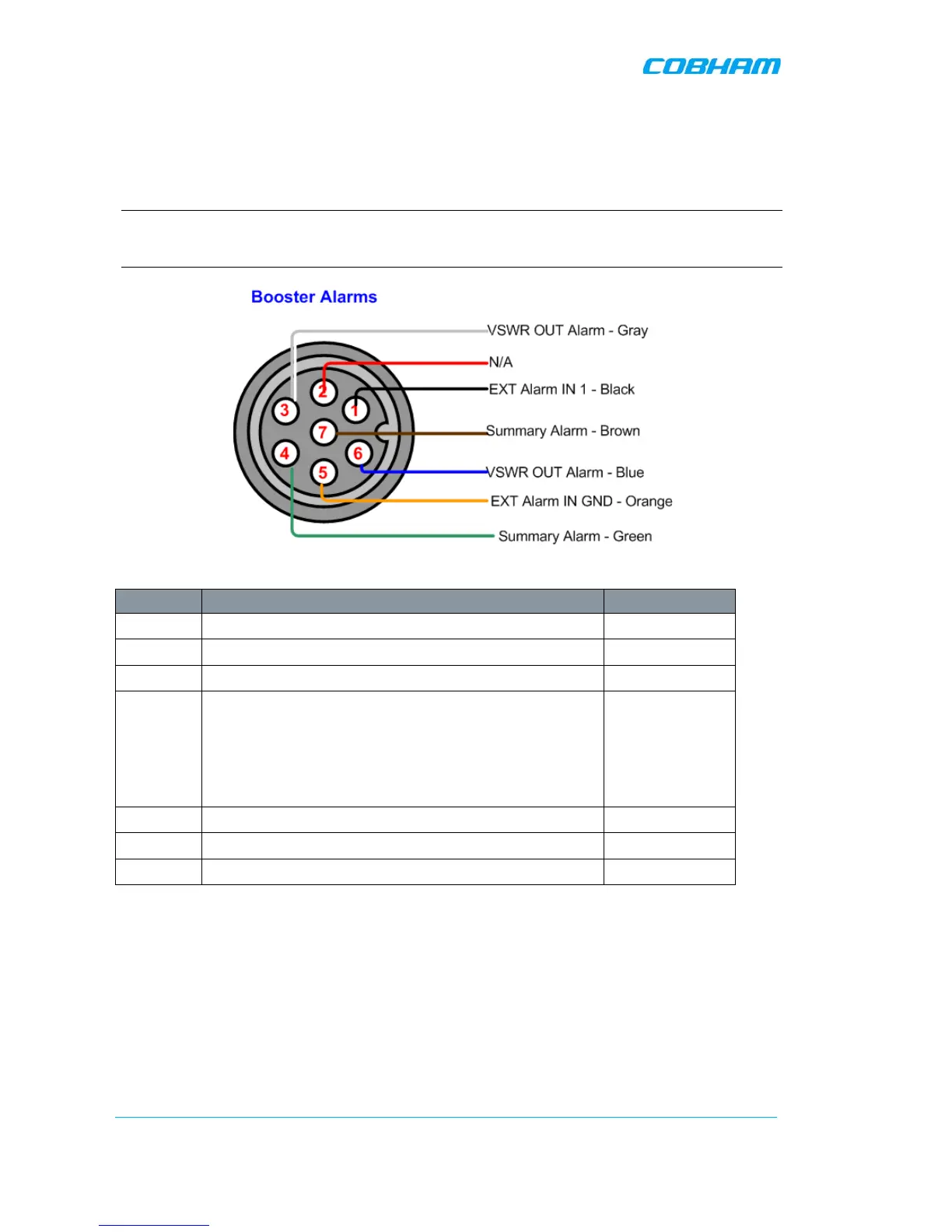
3.4.3.3 Booster Alarm Connector Pinout
Each alarm status is recognized by a separate wire-pair, where the colored wires are internally
connected with a 4.7 K ohm resistor (serves as a pull up resistor to +5V. The following figure shows
the Alarm connector pinout.
NOTE: EXT Alarm IN 1 can be used to provide SNMP alarm notification for one of the dry-contact
alarms of the UPS or Battery Charger. This is done by connecting the dry-contact alarm output and
then configuring EXT Alarm IN 1 as Normal = High according to section 5.5
Figure 3-18. D-MBR Alarm Connector Pinout
Pin No. Signal Name Wire Colour
1 External Alarm #1 Black
2 N/A
3 Dry Contact VSWR Alarm (Normally Closed)* White
4 Dry Contact Summary Alarm (Normally Closed)**
Triggered under one of the following conditions:
• PA current from FF
• Temperature High or Built-In-Test
• Power failure
Green
5 GND for External Alarm Orange
6 Dry Contact VSWR Alarm (Normally Closed)* Blue
7 Dry Contact Summary Alarm (Normally Closed)** Brown
*Dry Contact VSWR alarm connection is supported by a pair of wires (3,6). Also, Pins 3,6 can indicate Power Up
for approximately 1 minute when system is powered up by closing contacts 3,6.
** Dry Contact Summary alarm connection is supported by a pair of wires (4,7)