C002332_02_CR3 User Manual - 20
Save Settings
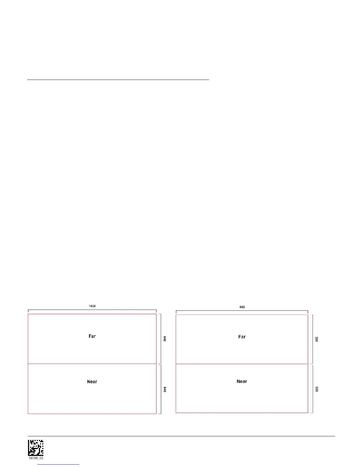
SXGA Imaging Area
VGA Imaging Area
3. Hold the CR3 still - DO NOT SWIPE OR MOVE THE READER. Press the trigger until the
CR3 beeps, indicating the code has been successfully decoded.
4. The reader may be optimized to your specific environment by scanning codes in Chapter 2.
1.10 - Imager Field of View and Resolution
The CR3’s dual field optical system may be modified based on your scanning environment. The CR3’s
megapixel imager may be set to the following three modes:
DOT Mode (Dynamic Optimization Technology): DOT dynamically changes the resolution of the reader
between VGA and SXGA. DOT adapts the resolution to you reading environment. This mode works best
if you are working with multiple types of symbologies and varying sizes of codes. If you are scanning
mostly medium to large 2D or 1D codes you may want to choose VGA. If you are scanning mostly small
or densely packed codes, SXGA may be the better choice. It is recommended to experiment with all three
modes to determine the best reading performance for your application.
SXGA Mode: In standard SXGA mode (default), the 1.3 Million Pixel imager is divided into near field and
far field decode zones. In each zone the resolution is 1024 x 640 pixels (see figure 1.16). In this mode of
operation the reader utilizes the highest resolution creating the widest working range on bar code and 2-
dimensional symbols of all densities. The trade-off is the amount of time the reader spends processing the
image. This time can be reduced by optimization functions:
If only the near field is used (small, high density symbols), the far field image can be ignored. If only the
far field is used (large, lower density symbols), the near field can be ignored. Further optimization may
be obtained by "windowing" the field to a smaller area. Each focal area may be narrowed by enabling the
windowing feature found in section 9.3.
VGA Mode: In VGA mode (optional selection), the 1.3 Million Pixels are sampled on a 4-to-1 basis. This
greatly reduces the amount of time necessary for the transfer of the image to the CPU and the resulting
processing time (figure 1.17). The trade-off for this increased speed is a reduction in resolution and
working range.
Figure 1.16
Figure 1.17