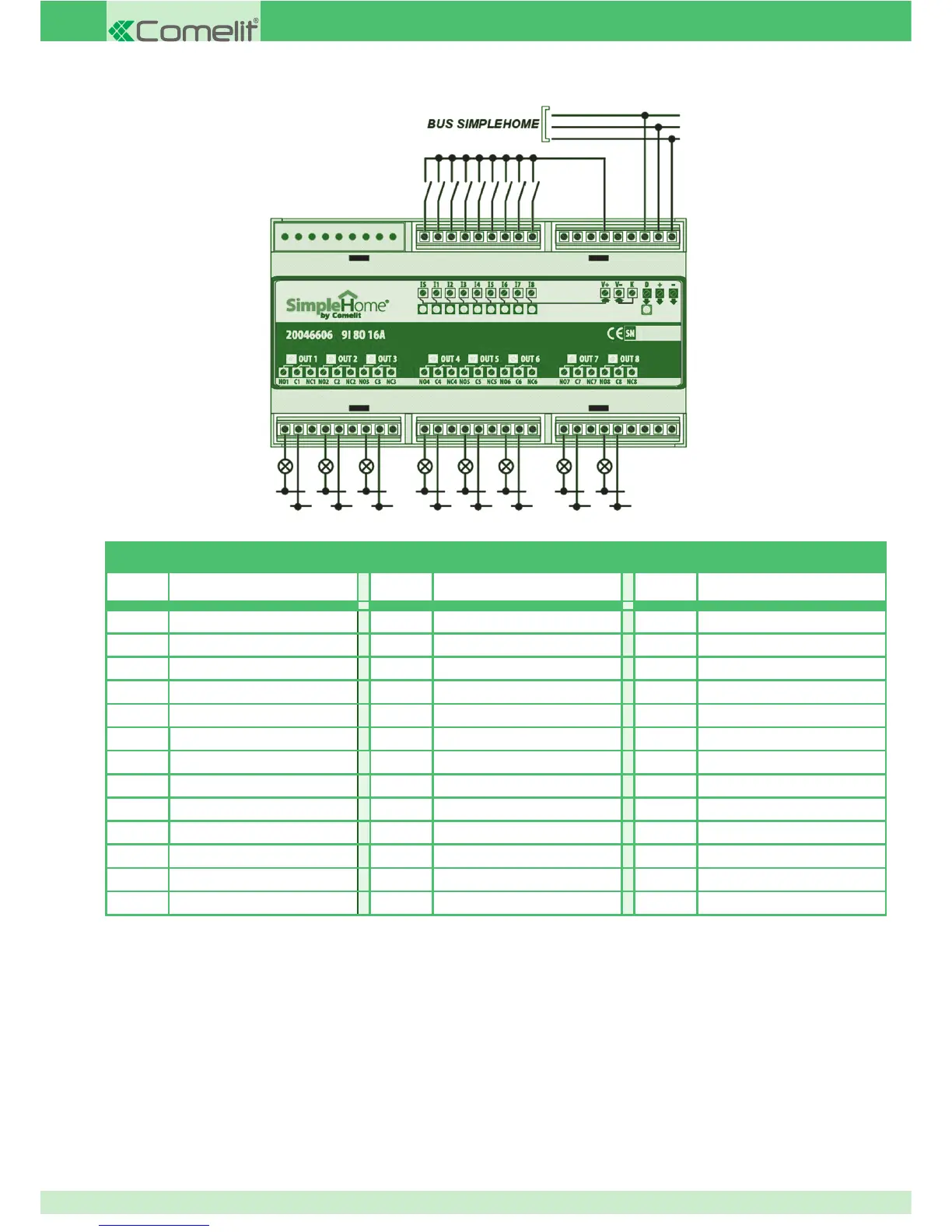
DIGITAL MODULE
Term. Function Term. Function Term. Function
- BUS power supply negative I1 Input 1 NC4 Output 4 – NC contact
+ BUS power supply +24 Vdc IS Multiple command (scenario) NO5 Output 5 – NO contact
D BUS data line NO1 Output 1 – NO contact C5 Output 5 – Common
K Common C1 Output 1 – Common NC5 Output 5 – NC contact
V- Support negative NC1 Output 1 – NC contact NO6 Output 6 – NO contact
V+ +24 Vdc support NO2 Output 2 – NO contact C6 Output 6 – Common
I8 Input 8 C2 Output 2 – Common NC6 Output 6 – NC contact
I7 Input 7 NC2 Output 2 – NC contact NO7 Output 7 – NO contact
I6 Input 6 NO3 Output 3 – NO contact C7 Output 7 – Common
I5 Input 5 C3 Output 3 – Common NC7 Output 7 – NC contact
I4 Input 4 NC3 Output 3 – NC contact NO8 Output 8 – NO contact
I3 Input 3 NO4 Output 4 – NO contact C8 Output 8 – Common
I2 Input 2 C4 Output 4 – Common NC8 Output 8 – NC contact
N.B. The module must be programmed via the BUS line, using the SimpleHome/RS232 interface (20022611) and the SimpleProg
programming software.
Specifi cations are subject to change without notice.
green (bus)
red (+)
blue (-)
28