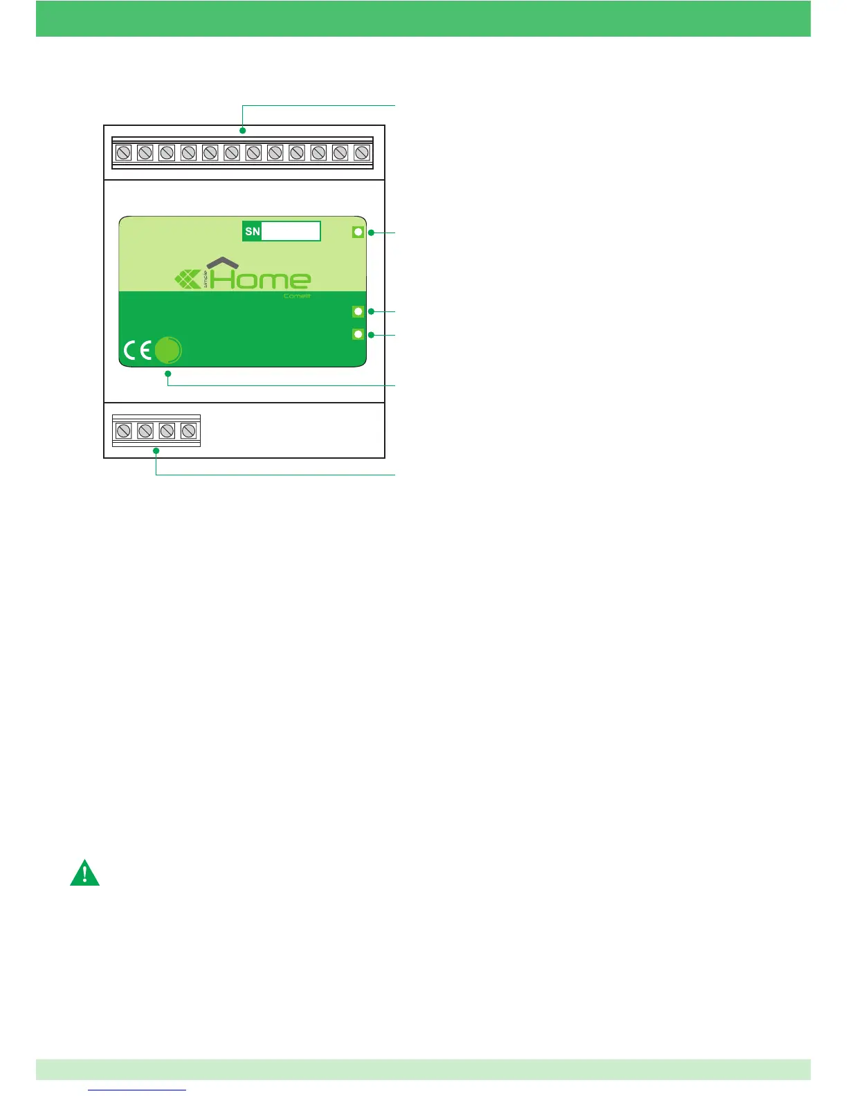
POWER / STATUS
RS232 / 485
BUS
RESET
20090334
SERIAL BRIDGE
1
2
3
4
1
5
1 Connection terminals:
- + : 12/24 Vdc power supply from home automation BUS or
alarm control unit.
D:
Simplehome BUS data terminal.
NC - NO - C: Voltage-free relay contacts.
I2:
Status input 2.
K:
Common status input.
I1:
Status input 1.
5:
Alarm control unit GND RS232.
3:
Alarm control unit RX RS232.
2:
Alarm control unit TX RS232.
+12 -12: Alarm serial port power supply terminals.
485 A/L+ - B/L -: Alarm supervisor connection terminals.
2 LED indicating data transmission over home automation BUS.
3 LED indicating data transmission to control units.
4 LED indicating operation:
• slow fl ashing: normal operation.
• quick fl ashing: Bootloader status.
5 Reset button.
CAUTION!! If the device is connected to the home
automation BUS power supply or the alarm control unit power
supply, the - terminal must be connected to the -12 terminal to
balance the reference negatives.
47