ENABLE MESSAGE RETRY: this tick can be used to set re-transmission of the command in the event that the module under control
does not respond. Under normal conditions, a single command is suffi cient to control the output. If the message is not received by
the module, and therefore the module sending the command does not receive feedback that the command has been carried out
successfully, the command will be sent again up to a maximum of 3 times. We recommend that this tick is always enabled, for greater
security in terms of the commands sent.
ENABLE ZONE BROADCAST: this tick enables transmission, over the BUS, of the status of the outputs activated following a zone
command received by the module. We recommend enabling this tick when zone commands have been programmed for the system
and supervisors (for example Planux Manager, Serial Bridge, etc...) are installed. This re-transmission carried out by the module
receiving the command may be important in order to update the status of the outputs on the supervisors.
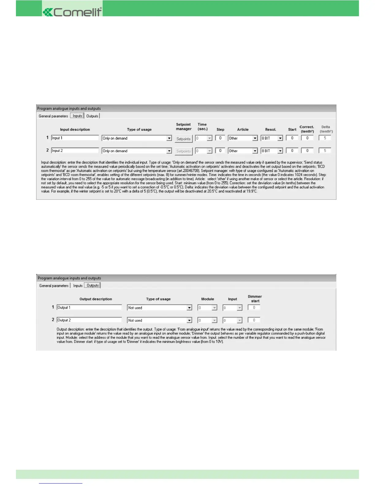
INPUTS
HIGH-PRECISION ROOM THERMOSTAT: this option allows you to view and adjust the temperature of the temperature sensor 20046708
connected to module 20046707.
AUTOMATIC ACTIVATION ON SETPOINTS: this option can be used to select setpoints (4 upward and 4 downward) for the 0-10 V input, for
the activation or deactivation of an output when the specifi ed setpoint is exceeded. For example, it can be used to activate an output
when a certain brightness level is detected by a 0-10 V dawn/dusk sensor. This means it is possible to activate 4 different outputs when
the value recorded by the 0-10 V input increases, and deactivate the same (or different) outputs when the 0-10 V signal decreases. The
value recorded by the analogue input is converted to an 8-bit value, from 0 to 255. The value recorded and converted to an 8-bit format
cannot be viewed on the supervisor devices.
OUTPUTS
OUTPUT DESCRIPTION: enter a general description of the device connected to the corresponding output.
TYPE OF USAGE: set the operating mode for the 0-10 V analogue output.
FROM ANALOGUE INPUT: this option can be used so that the 0-10 V output on the module is followed by the corresponding 0-10 V input
on the same module. If the 0-10 V input is adjusted, for example to 5 V, the output will also adjust until it reaches the 5 V value. If output
2 on the module is set as "from analogue input", the output will follow the status of input 2.
FROM INPUT ON ANALOGUE MODULE: this option, as with the previous option, can be used to create a 0-10 V output that follows the
status of a 0-10 V input. In this case the input should not be on the output module, but on a different module (for example, an input
on module 20046707). Every change to the analogue input results in an identical change to the output. The module number and the
number of the input on the module which should be displayed when controlling the output must be set in the "module" and "Input" fi elds
on the same programming screen.
DIMMER: the setting used most frequently for the 0-10 V output is “dimmer”, as it enables connection of the 0-10 V output to a dimmer
with a 0-10 V input and therefore allows control of a light source such as a dimmer with the option of control and adjustment from a
72