CDM-570/570L Satellite Modem with Optional IP Module Revision 4
Connector Pinouts MN/CDM570L.IOM
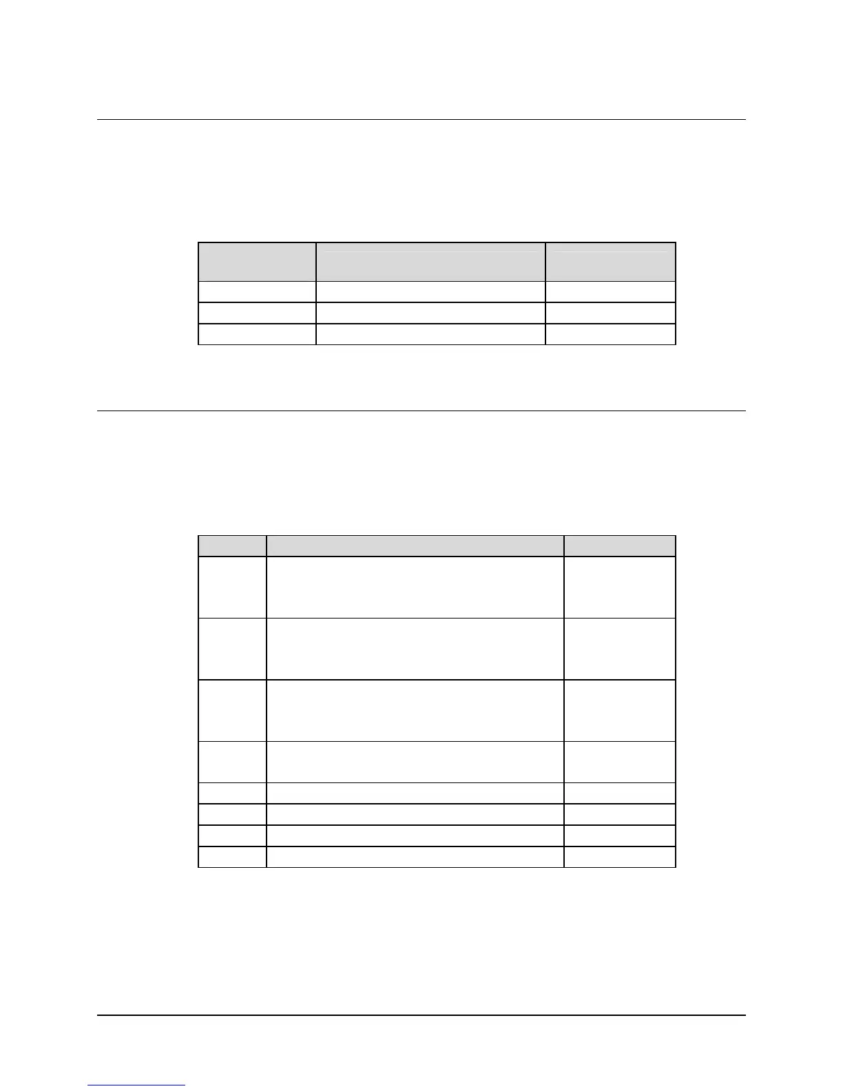
5.5 BNC Connectors
There are three BNC connectors located on the rear panel of the modem. Refer to
Table 5-5 for pin assignments.
Table 5-5. BNC Connectors
BNC
Connector
Description Direction
EXT REF External Reference Input In
G.703 Out Rx G.703 (Unbalanced) Out
G.703 In Tx G.703 (Unbalanced) In
5.6 Unit Alarms
Unit alarms are provided on a 15-pin male connector located on the rear panel of the
modem. Refer to
Table 5-6 for pin assignments.
Table 5-6. Alarm Interface Connector Pin Assignments
Pin # Signal Function Name
8
15
7
Rx Traffic (De-energized, Faulted)
Rx Traffic (Energized, No Fault)
Rx Traffic
RX-NC
RX-NO
RX-COM
14
6
13
Tx Traffic (De-energized, Faulted)
Tx Traffic (Energized, No Fault)
Tx Traffic
TX-NC
TX-NO
TX-COM
5
12
4
Unit Fault (De-energized, Faulted)
Unit Fault (Energized, No Fault)
Unit Fault
UNIT-NC
UNIT-NO
UNIT-COM
11
3
Rx I Channel (Constellation monitor)
Rx Q Channel (Constellation monitor)
RX-I
RX-Q
10 No Connection N/C
2 AGC Voltage (Rx signal level, 0 to 10 volts) AGC
9 EXT Carrier OFF EXT-OFF
1 Ground GND
5–4