32 Condair CDC, CDC-NA, CDC-ST and CDC-SL
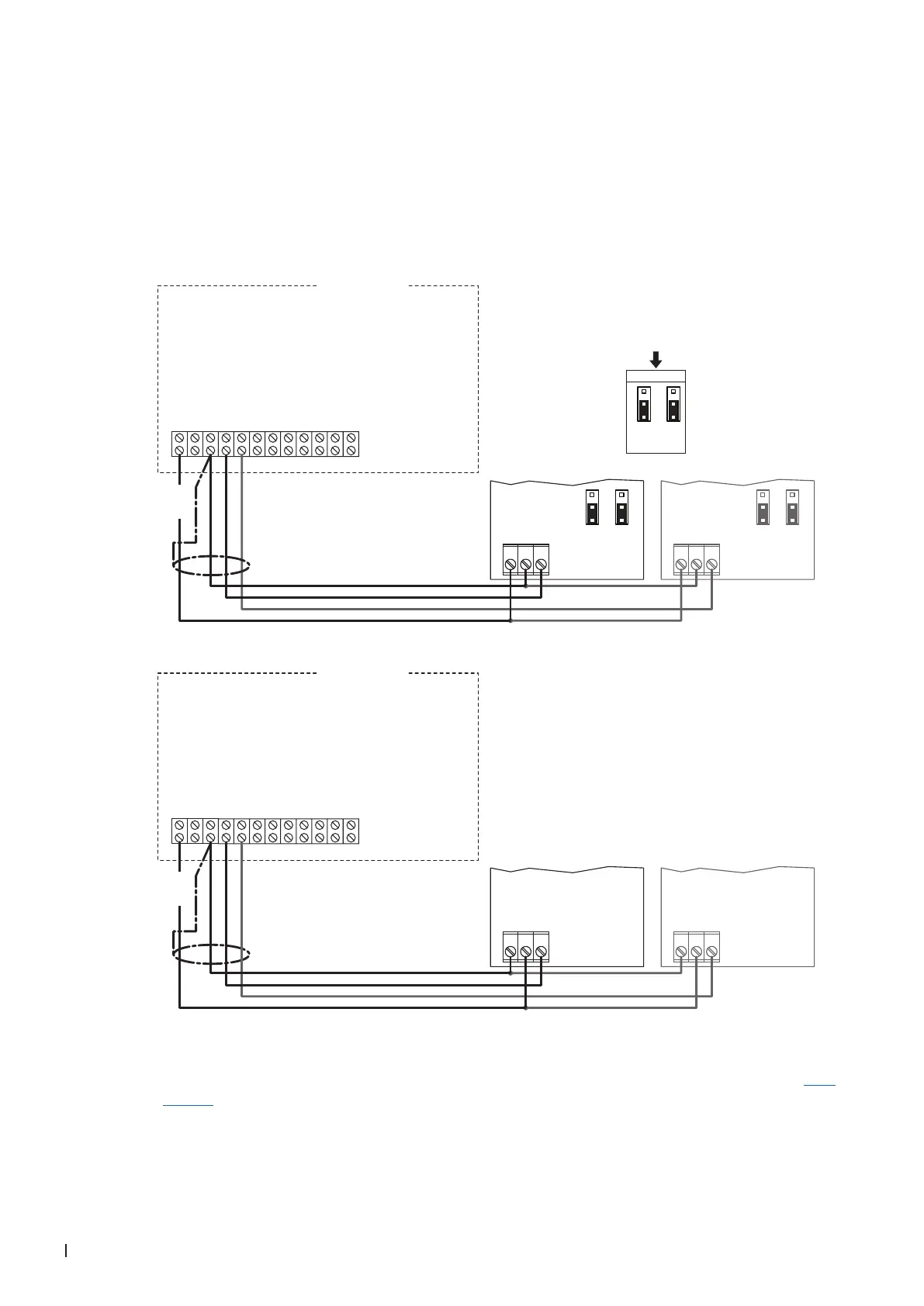
2.8.6 Connecting the CDC or CDC-NA to the Condair SE
1. Connect the CDC or CDC-NA (signal Y1) to the corresponding terminals of the Condair SE accord-
ing to the appropriate wiring diagram (see below).
Note: The voltage supply of the CDC or CDC-NA is established via the terminals "24 VAC" and
"Ground" of the terminal block or via an external 24 V AC/DC voltage supply.
Note: In case of humidity control with limitation of the supply air humidity, a second CDC or CDC-NA
duct humidity sensor (signal Y2) is to be connected according to the appropriate wiring diagram below.
2. Only for CDC: Set the output signal of the CDC to "0-10V" using the Jumpers JP1 and JP3 on the
control board of the CDC.
Note: other output signal settings (e.g. 4-20mA) are also possible, see CDC jumper settings in Sec-
tion 2.7.
12
11
10
9
8
76
54
321
24VAC
0-10V VDC Out
On/Off Loop
Ground
Actuator Power
Actuator Power
Control Signal
Limit Signal (SETC only)
Full Tank Blowdown
Ground
Ground
5 VDC
Condair SE
***
0...10V
JP1
2
3
1
JP3
2
3
1
24 VAC
12
11
10
9
8
76
54
321
24VAC
0-10V VDC Out
On/Off Loop
Ground
Actuator Power
Actuator Power
Control Signal
Limit Signal (SETC only)
Full Tank Blowdown
Ground
Ground
5 VDC
Condair SE
24V AC/DC
0V/GND
H OUT
JP1
2
3
1
JP3
2
3
1
***
1 2 3
24V AC/DC
0V/GND
H OUT
JP1
2
3
1
JP3
2
3
1
***
1 2 3
24 VAC
0V/GND
24V AC/DC
H OUT
1 2 3
0V/GND
24V AC/DC
H OUT
1 2 3
CDC (Signal Y1)
CDC-NA (Signal Y1)
CDC (Signal Y2)
CDC-NA (Signal Y2)