34 Condair CDC, CDC-NA, CDC-ST and CDC-SL
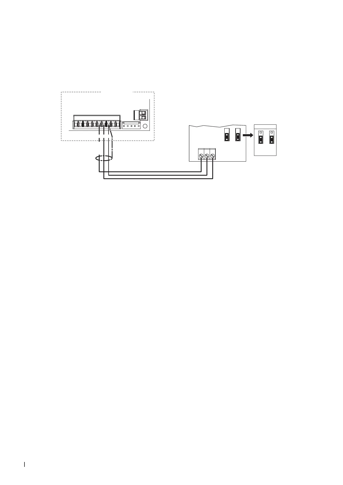
2.8.8 Connecting the CDC to the Condair RM
1. Connect the CDC (signal Y) to the corresponding terminals of terminal block "X1" of the Condair RM
according to the wiring diagram below.
Note: The voltage supply of the CDC is established via the terminals "6" and "8" of the terminal block
"X1" or via an external 24 V AC/DC voltage supply.
X6
X5
X1
Condair RM
24V AC/DC
0V/GND
H OUT
JP1
2
1
JP3
2
1
***
1 2 3
***
0...10V
JP1
2
3
1
JP3
2
3
1
876
24 VDC
Driver board
Condair RM
CDC (Signal Y)
2. Set the Condair RM into operation and set in the unit software under "Engineering > Steam Genera-
tor> Steaming Settings" the parameters "Input signal" to "0-10V" (or to output signal set on CDC),
"Control Mode" to "rH" and "PID Type" to "PI" as well as in the user menu "Set point value" to
the desired value (refer to the Condair RM operation manual).