35Condair CDC, CDC-NA, CDC-ST and CDC-SL
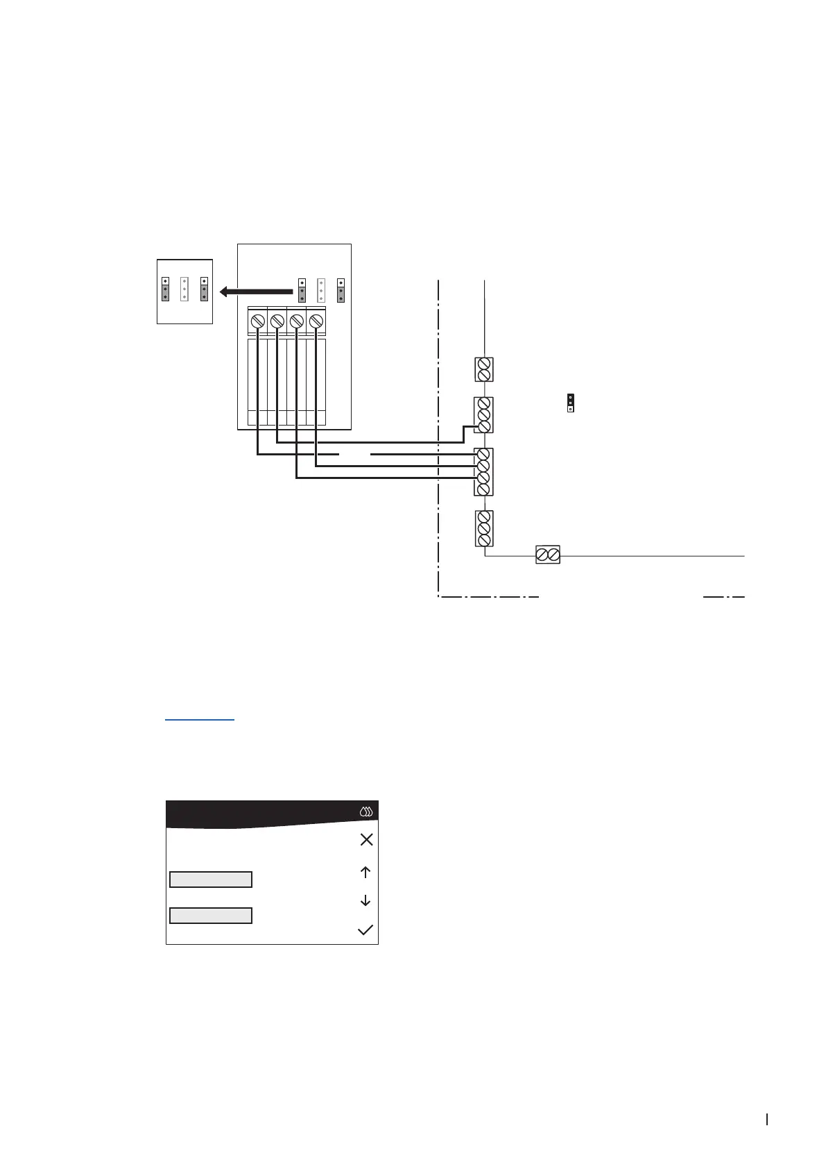
2.8.9 Connecting the CDC-ST to the Condair MD
1. Connect the CDC (signal Y) to the corresponding terminals of terminal block "X11" and "X12" on the
power board of the Condair CP3mini according to the wiring diagram below.
Note: The voltage supply of the CDC-ST is established via the terminal "24V+" on terminal block
"X12" and terminal "GND" on terminal block "X13" or via an external 24 V AC/DC voltage supply.
X11
X10
X12
X13
JP4
X15
Hygro
24V+
Temp
Hum 1
Hum 2
10V/24V+
GND
GND
GND
GND
Leak
24V
24V
Safety
10V24V
JP1 JP3 JP3
24V AC/DC
1
0V / GND
G
G0
2
AO RH
3
AO T
U1
U2
4
24 VDC
0...10V
JP1 JP3 JP3
Driver board Condair MD
Hydraulic unit Condair MD
2. Set the jumper "JP4" on the driver board in the hydraulic unit of the Condair MD to "24V".
3. Set the output signal of the CDC-ST with jumpers "JP1" and "JP3" on the control board of the CDC-
ST to "0-10V"
Note: other output signal settings (e.g. 4-20mA) are also possible, see CDC-ST jumper settings in
Section 2.7.
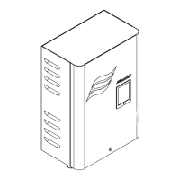
4. Set the Condair MD into operation and set "Control Mode" in the "User Settings" menu (Path: "User
Settings > Operation > Control Mode") to "Inlet Air" (for supply air control) or "Ext Air" (for extract air
control) . Conrm selection with the <> button.
CDC-ST (Signal Y)
Control Mode
Ext. Cntrl
On / Off
Ext Setpnt
Ext Air
Inl+Ext. Hyg
Inlet Air