36 Condair CDC, CDC-NA, CDC-ST and CDC-SL
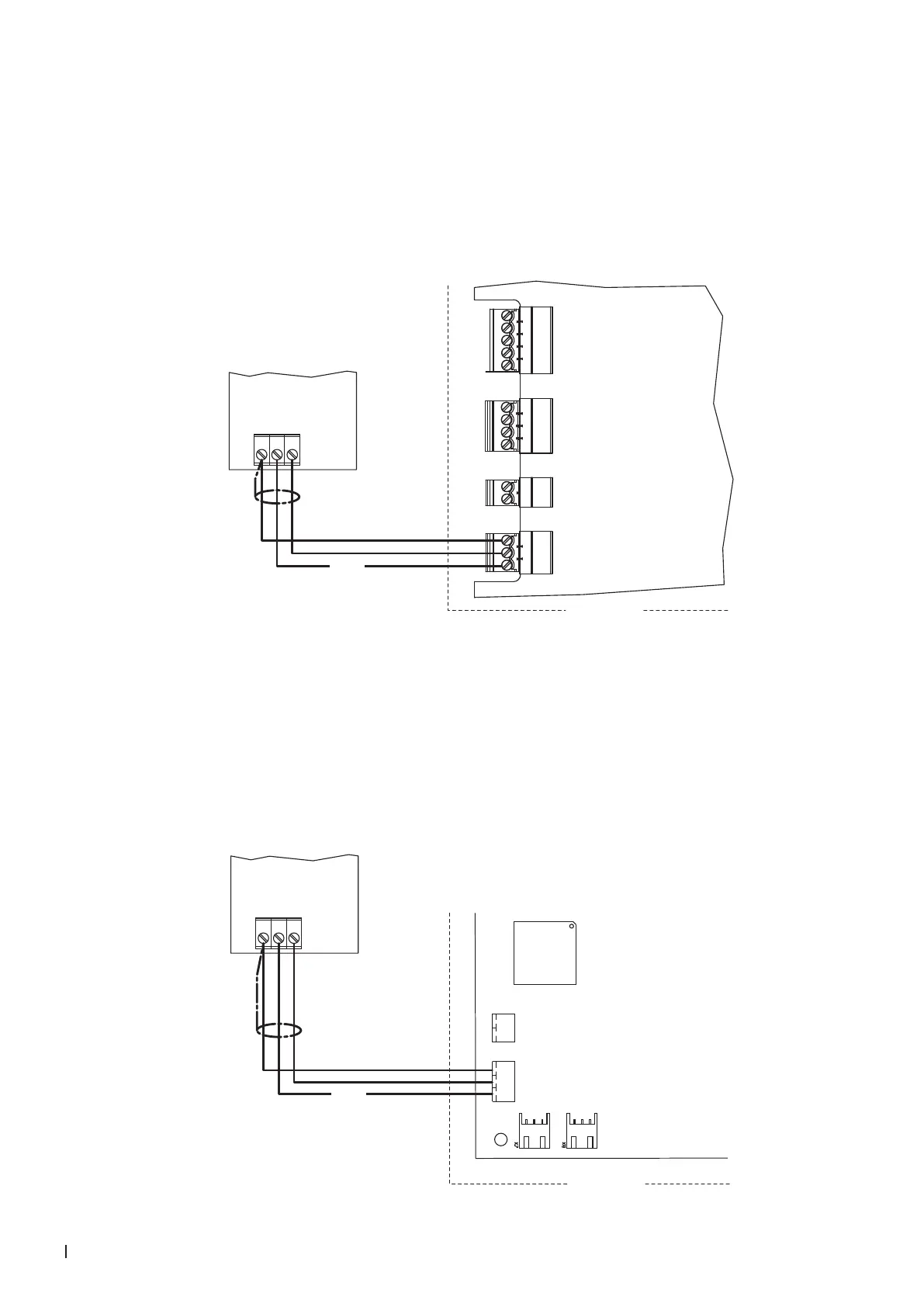
2.8.10 Connecting the CDC-SL am Condair RH
Connect the CDC-SL (signal Y) to the corresponding terminals of the terminal block "X2" on the driver
board of the Condair RH according to the wiring diagram below. The voltage supply of the CDC-SL is
established via the terminals "24 VDC" and "GND" or via an external 24 V AC/DC voltage supply.
Note: The CDC-SL works with a xed control signal range of 2-10 V. The corresponding sensor setting
can be adjusted using the HumiLife app.
24V AC/DC
0V/GND
H OUT
1 2 3
24 VDC
Condair RH
24V
HUM
GND
X4
X5
X3
X2
SC
SC
24V
LIM
GND
GND
24V
EXT
GT
RF
GF
Driver board
Condair RH
CDC-SL (Signal Y)
2.8.11 Connecting the CDC-SL am Condair RE
Connect the CDC-SL (signal Y) to the corresponding terminals of the terminal block "X6" on the driver
board of the Condair RE according to the wiring diagram below. The voltage supply of the CDC-SL is
established via the terminals "24 VDC" and "GND" or via an external 24 V AC/DC voltage supply.
Note: The CDC-SL works with a xed control signal range of 2-10 V. The corresponding sensor setting
can be adjusted using the HumiLife app.
24V AC/DC
0V/GND
H OUT
1 2 3
Condair RE
24 VDC
X6
X5
GND
HUM
24VDC
SC
SC
Driver board
Condair RE
CDC-SL (Signal Y)