43Condair CRC and CRC-NA
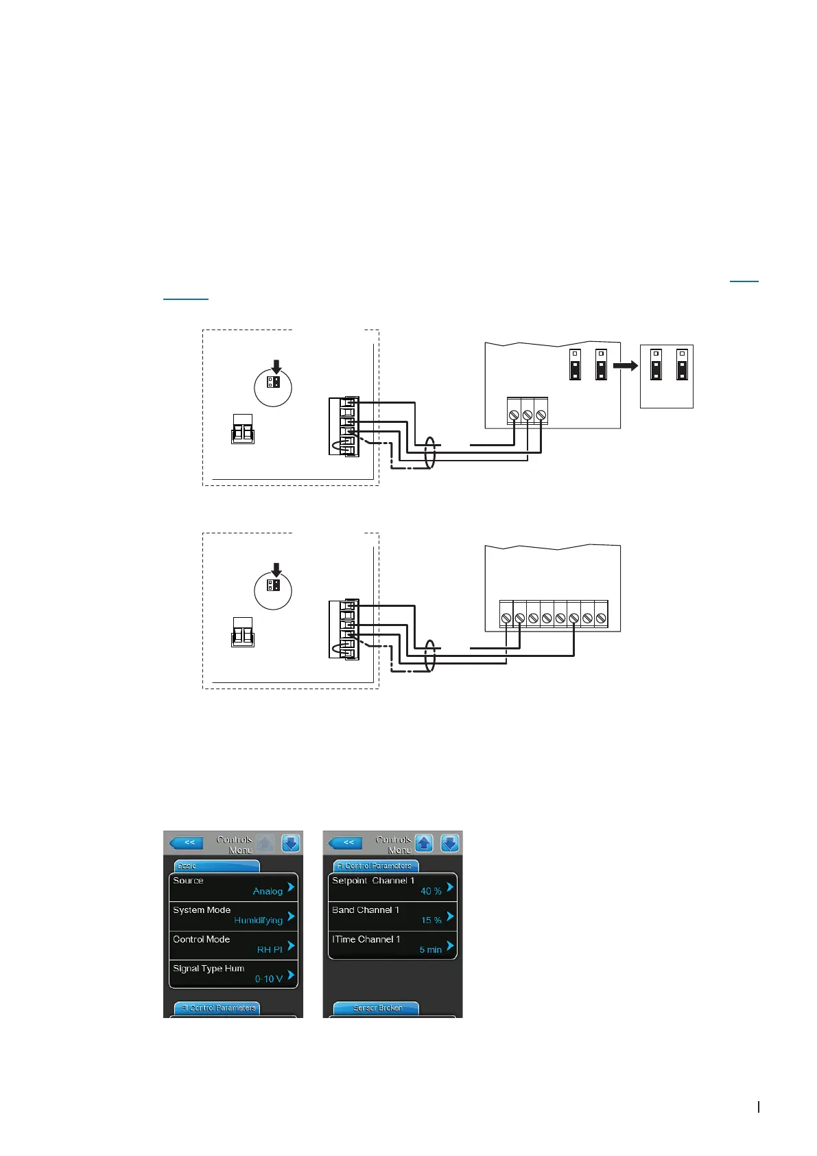
3.8.2 Connecting the CRC or CRC-NA to the Condair ME
1. Connect the CRC or CRC-NA according to the appropriate wiring diagram (see below) to the cor-
responding terminals of the terminal block "X16" on the driver board of the Condair DL.
Note: The voltage supply of the CRC or CRC-NA is established via the terminals "24/10V" and "GND"
of terminal block "X16" or via an external 24V AC/DC voltage supply.
2. On the driver board of the Condair ME: set a Jumper on JP4-24V and remove the Jumper on JP5-
10V (if a jumper is set).
3. Only for CRC: Set the output signal of the CRC to "0-10V" using the Jumpers JP1 and JP3 on the
control board of the CDC.
Note: other output signal settings (e.g. 4-20mA) are also possible, see CRC jumper settings in Sec-
tion 3.7.
24V AC/DC
0V/GND
H OUT
JP1
2
3
1
JP3
2
3
1
1 2 3
0...10V
JP1
2
3
1
JP3
2
3
1
X1
X16
JP5: 10V
JP4: 24V
SC2
SC1
24/10 V
TMP
GND
HUM
24V E
Enable
24 VDC
Condair ME
X1
X16
JP5: 10V
JP4: 24V
SC2
SC1
24/10 V
TMP
GND
HUM
24V E
Enable
24 VDC
24V AC/DC
0V/GND
A0 2-10V
1 2 3 4 5 6 7 8
Driver board Condair ME
CRC-NA
CRC
Driver board Condair ME
4. Set the Condair ME into operation, go to the control menu of the unit software and set the param-
eters "Source" to "Analog", "System Mode" to "Humidifying", "Control Mode" to "RH PI", "Signal
Type Hum" to "0-10V" (or to output signal set on CRC) or "2-10V" (for CRC-NA) and the parameters
"Setpoint Channel 1", "Band Channel 1" and "ITime Channel 1" to the desired values (refer to the
Condair ME operation manual).