46 Condair CRC and CRC-NA
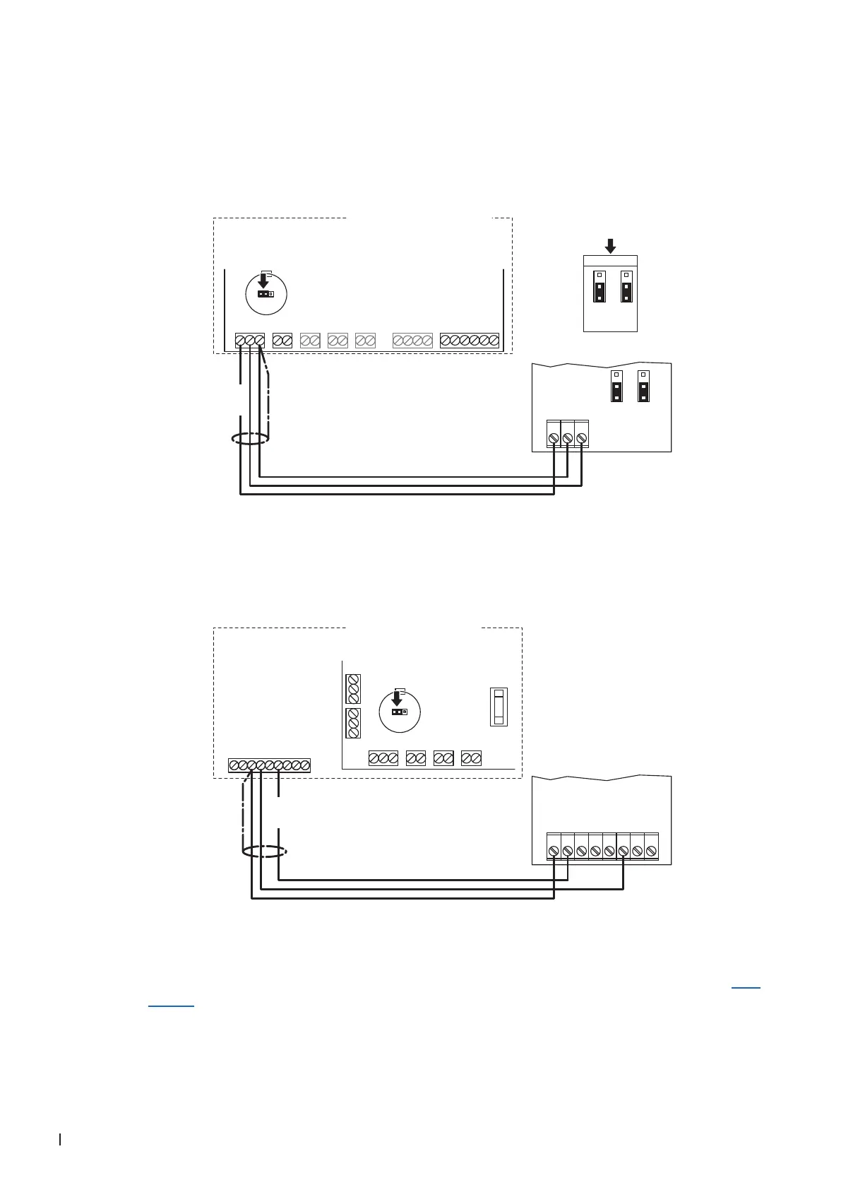
3.8.4 Connecting the CRC or CRC-NA to the Condair EL/EL OC
1. Connect the CRC to the corresponding terminals on the driver board of the Condair EL/EL OC (ROW)
according to the following diagram.
Note: The voltage supply of the CRC is established via the terminals "V+" and "GND" of terminal
block "X8" or via an external 24 V AC/DC voltage supply.
MAINS SUPPLY
L N SC1SC2PEPE
MODULE B
24VDCBLOWERLIMIT ENABLECONTROL
V+
X8
X9
X12
X11
X10
X7
X1
INGND IN GND 24V IN24V IN 24V GND
Condair EL/EL OC (ROW)
24V 10V
JP1
JP3
***
0...10V
JP1
2
3
1
JP3
2
3
1
24 VDC
24V AC/DC
0V/GND
H OUT
JP1
2
3
1
JP3
2
3
1
1 2 3
Driver board Condair EL/EL OC Module A
CRC
Connect the CRC-NA to the appropriate terminals of the terminal block "XE2" of the Condair EL/EL
OC (NA) according to the following diagram.
Note: The voltage supply of the CRC-NA is established via the terminals "24VDC/10VDC" and "GND"
of terminal block "XE2" or via an external 24 V AC/DC voltage supply.
24V AC/DC
0V/GND
A0 2-10V
1 2 3 4 5 6 7 8
Condair EL/EL OC (NA)
BLOWERLIM. SIGN. ON/OFFCONT. SIGN.
V+
X8
X9
X12
X11
IN GND IN GND 24V IN24V IN
RS485-1 RS485-2
24V 10V
JP1
JP3
GND D–D+ GND D–D+
24VAC
Sec. Loop
GND
CH1
CH2
24VDC/10VDC
GND
BP Sec. Loop
BP Sec. Loop
1 2 3 4 5 6 7 8 9
XE2
24 VDC
Driver board
Condair EL/EL OC
Module A
CRC-NA
2. Set a jumper on JP1-24V on the driver board of the Condair EL/EL OC.
3. Only for CRC: Set the output signal of the CRC to "0-10V" using the Jumpers JP1 and JP3 on the
control board of the CRC.
Note: other output signal settings (e.g. 4-20mA) are also possible, see CRC jumper settings in Sec-
tion 3.7.