48 Condair CRC and CRC-NA
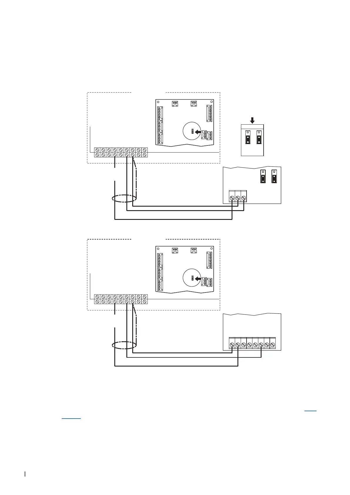
3.8.5 Connecting the CRC or CRC-NA to the Condair GS
1. Connect the CRC or CRC-NA to the corresponding terminals of the Condair GS according to the
appropriate wiring diagram (see below).
Note: The voltage supply of the CRC or CRC-NA is established via the terminals "+24 VDC" and
"GND" of the terminal block or via an external 24 V AC/DC voltage supply.
24V AC/DC
0V/GND
A0 2-10V
1 2 3 4 5 6 7 8
1
2
3
4
5
67
89
24VAC
Safety Loop
GND
GND
FTBD
CH1
CH2
+24 VDC
Condair GS
***
0...10V
JP1
2
3
1
JP3
2
3
1
24 VDC
J1
J10
J3
J7
J8
J1
J2
JP2
24V 10V
24V AC/DC
0V/GND
H OUT
JP1
2
3
1
JP3
2
3
1
***
1 2 3
1
2
3
4
5
67
89
24VAC
Safety Loop
GND
GND
FTBD
CH1
CH2
+24 VDC
Condair GS
24 VDC
J1
J10
J3
J7
J8
J1
J2
JP2
24V 10V
Driver board
Condair GS
Driver board
Condair GS
CRC
CRC-NA
2. On the driver board of the Condair GS: set a Jumper on JP2-24V.
3. Only for CRC: Set the output signal of the CRC to "0-10V" using the Jumpers JP1 and JP3 on the
control board of the CRC.
Note: other output signal settings (e.g. 4-20mA) are also possible, see CRC jumper settings in Sec-
tion 3.7.