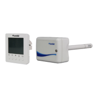
77Condair RCC and RCC-NA
5.8.5 Connecting the RCC or RCC-NA to the Condair US
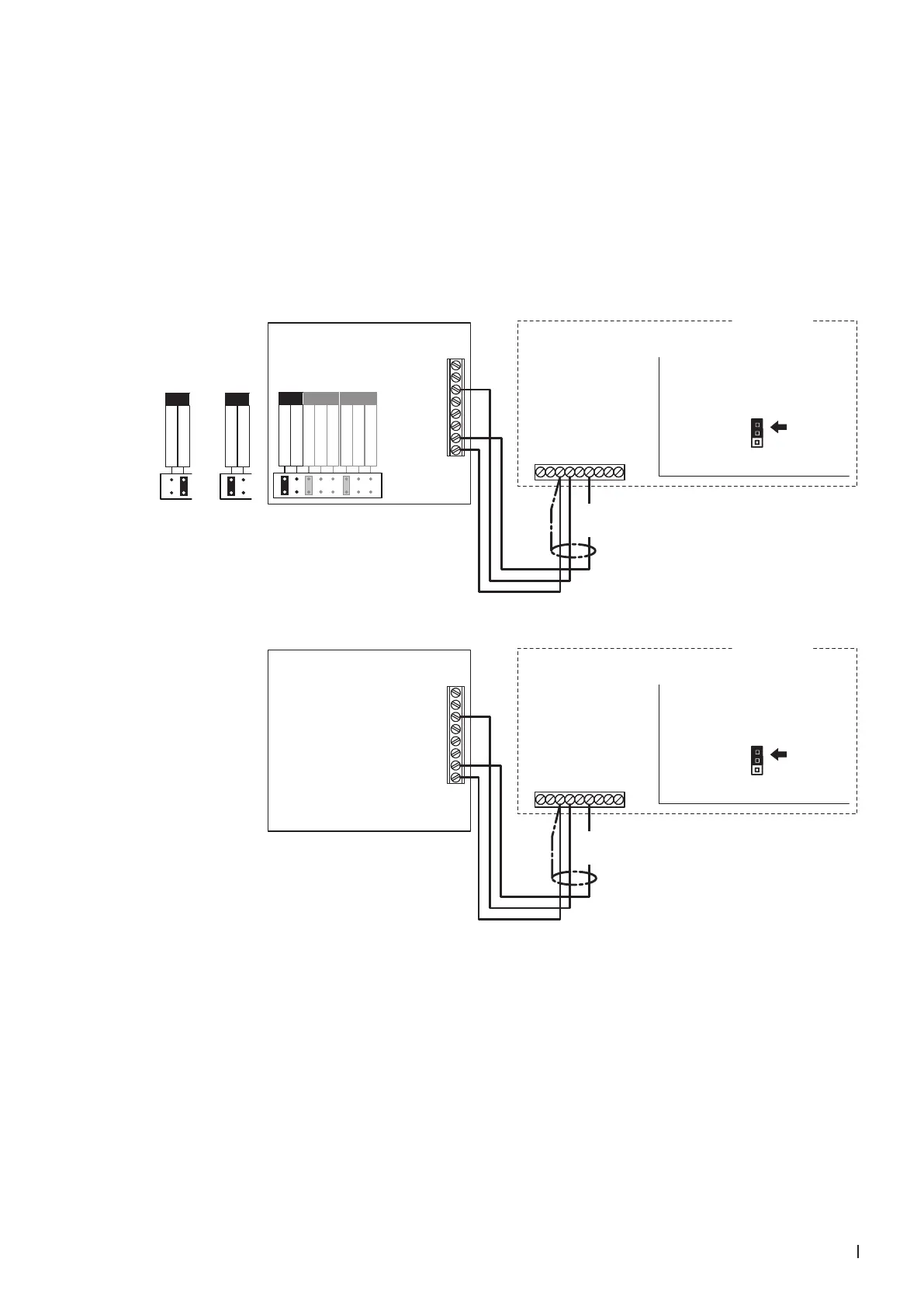
1. Connect the Condair RCC or RCC-NA to the corresponding terminals of terminal block "XE2" of the
Condair US according to the appropriate wiring diagram below.
Note: The voltage supply of the RCC or RCC-NA is established via the terminals "Control Signals
(V+)" and "Control Signals (GND)" of the terminal block "XE2" or via an external 24 V AC/DC volt-
age supply.
2. Set a jumper on "J1-24 V" on the control board of the Condair US.
3. Only for RCC: Set the output signal of the RCC to "0-10V" using the jumpers "AO".
J1
24V
10V
Condair US
Security (VDC)
External Safety Loop
Control Signal (GND)
Control Signal (IN)
Limit Signal (IN)
Control Signal (V+)
Limit Signal (GND)
Safety Circuit
Safety Circuit
1 2 3 4 5 6 7 8 9
XE2
J1
24V
10V
Condair US
Security (VDC)
External Safety Loop
Control Signal (GND)
Control Signal (IN)
Limit Signal (IN)
Control Signal (V+)
Limit Signal (GND)
Safety Circuit
Safety Circuit
1 2 3 4 5 6 7 8 9
XE2
8
7
UI2
6
5
4
3
2
1
UI1
AO1
24 V
0V/GND
RCC
**
0...10 V
0...20mA
RT or Dry-Contact
RT or Dry-Contact
UI1 UI2
0...10 V
0...20mA
0...10 V
0...20mA
AO
0...10V
**
0...10 V
0...20mA
AO
0...20mA
0...10 V
0...20mA
AO
24 VDC
8
7
UI2
6
5
4
3
2
1
UI1
AO1
24 V
0V/GND
RCC-NA
24 VDC
Control board
Condair US
Control board
Condair US