76 Condair RCC and RCC-NA
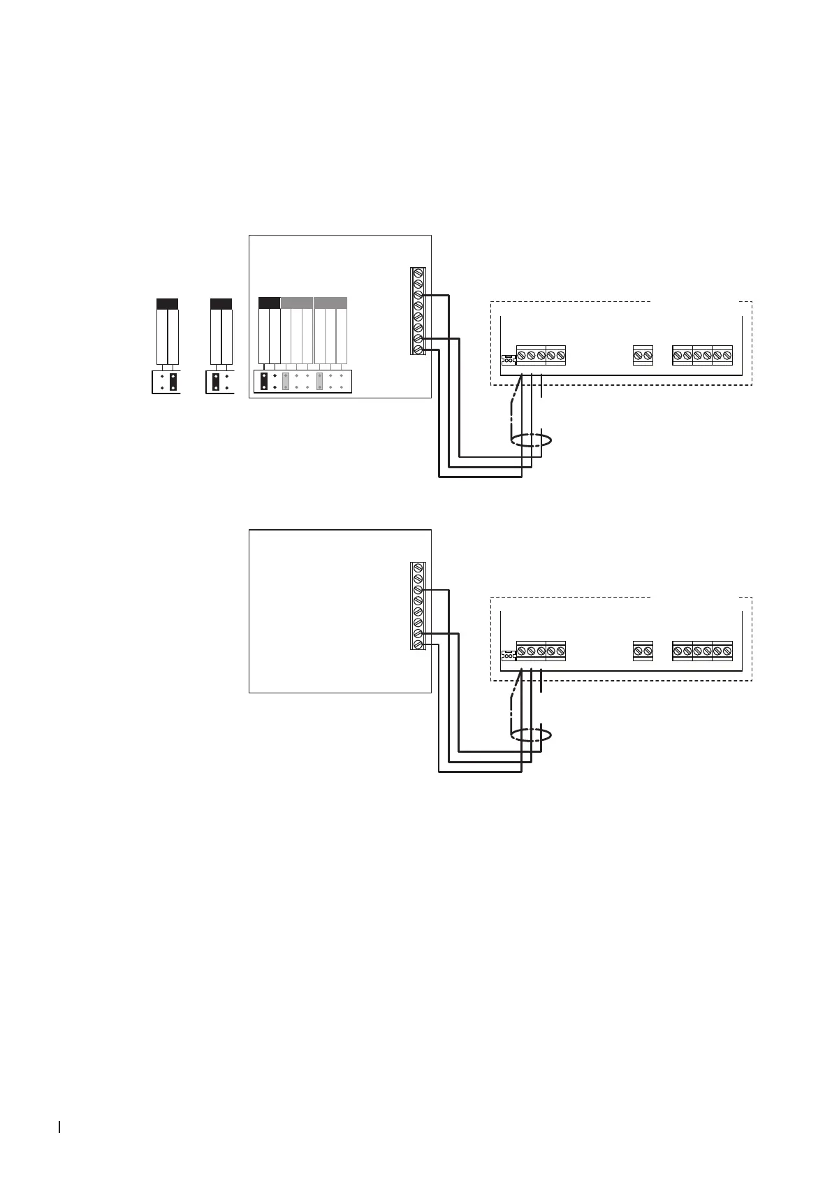
5.8.4 Connecting the RCC or RCC-NA to the Condair ABS3
1. Connect the Condair RCC or RCC-NA to the corresponding terminals on the control board of the
Condair ABS3 according to the appropriate wiring diagram below.
Note: The voltage supply of the RCC or RCC-NA is established via the terminals "24V" and "GND"
of the terminal block or via an external 24 V AC/DC voltage supply.
2. Only for RCC: Set the output signal of the RCC to "0-10V" using the jumpers "AO".
K1N L1 K2 K3
24V LEVELGND IN
NTC
Condair ABS3
K1N L1 K2 K3
24V LEVELGND IN
NTC
Condair ABS3
8
7
UI2
6
5
4
3
2
1
UI1
AO1
24 V
0V/GND
RCC
**
0...10 V
0...20mA
RT or Dry-Contact
RT or Dry-Contact
UI1 UI2
0...10 V
0...20mA
0...10 V
0...20mA
AO
0...10V
**
0...10 V
0...20mA
AO
0...20mA
0...10 V
0...20mA
AO
24 VDC
8
7
UI2
6
5
4
3
2
1
UI1
AO1
24 V
0V/GND
RCC-NA
24 VDC
Control board
Condair ABS3
Control board
Condair ABS3