75Condair RCC and RCC-NA
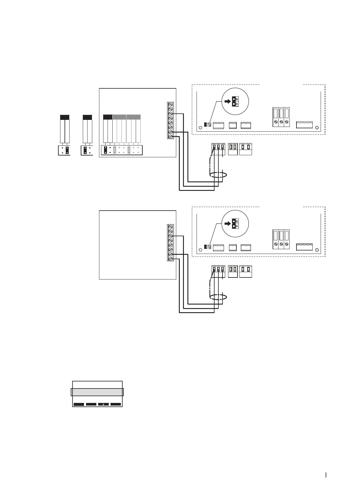
5.8.3 Connecting the RCC or RCC-NA to the Condair CP3mini
1. Connect the Condair RCC or RCC-NA to the corresponding terminals of terminal block "X1" on the
power board of the Condair CP3mini according to the appropriate wiring diagram below.
Note: The voltage supply of the RCC or RCC-NA is established via the terminals "V+" and "GND"
of terminal block "X1" or via an external 24 V AC/DC voltage supply.
CONT.SIGN LIM.SIGN
V+ LIMGND
GND CTRL
X1 X4 X6
CTRL V+
1 21 21 2 3
GND
BASIC
0-10V
On/Off
24V
5V
PRO
JP4
JP3
JP2
JP1
LIMGND SC1SC2
SAFETY
SC1SC2
24V
5V
JP2
JP1
Condair CP3 mini
PWR
MAIN SUPPLY
X9
L
N PE
X8
N L SW N SWL
8
7
UI2
6
5
4
3
2
1
UI1
AO1
24 V
0V/GND
RCC
**
0...10 V
0...20mA
RT or Dry-Contact
RT or Dry-Contact
UI1 UI2
0...10 V
0...20mA
0...10 V
0...20mA
AO
0...10V
**
0...10 V
0...20mA
AO
0...20mA
0...10 V
0...20mA
AO
24 VDC
CONT.SIGN LIM.SIGN
V+ LIMGND
GND CTRL
X1 X4 X6
CTRL V+
1 21 21 2 3
GND
BASIC
0-10V
On/Off
24V
5V
PRO
JP4
JP3
JP2
JP1
LIMGND SC1SC2
SAFETY
SC1SC2
24V
5V
JP2
JP1
Condair CP3 mini
PWR
MAIN SUPPLY
X9
L
N PE
X8
N L SW N SWL
8
7
UI2
6
5
4
3
2
1
UI1
AO1
24 V
0V/GND
RCC-NA
24 VDC
Power board
Condair CP3mini
Power board
Condair CP3mini
2. On the power board of the Condair CP3mini: set a Jumper on JP2-24 V and remove the Jumper on
JP1-5V (if a jumper is set).
3. Only for RCC: Set the output signal of the RCC to "0-10V" using the jumpers "AO".
4. Set the Condair CP3mini into operation, go to the setup level of the unit software and set the pa-
rameters "Hum.Control" to "External", "Controlsign." to "0-10V" (refer to the Condair CP3mini
installation and operation manual).
Controls
Hum.Control :External
Controlsign.:0-10V
Lim. Control:O
SignalSource:Analog
Esc Set